


Installation
13
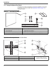
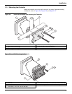
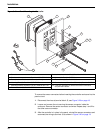
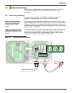
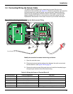
7. Reinstall the high-voltage barrier and latch to secure.
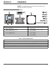
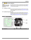
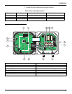
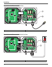
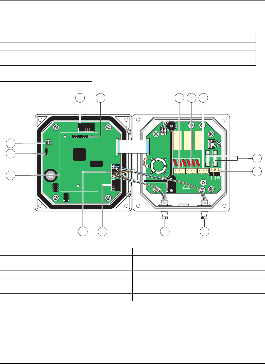
Figure 3-14 Wiring Connections
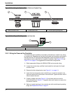
Table 3-2 Power Wiring Information
Terminal Number Terminal Description Wire Color Code for North America Wire Color Code for Europe
1 Hot (L1) Black Brown
2 Neutral (N) White Blue
3 Protective Earth (PE) Green Green w/yellow tracer
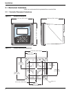
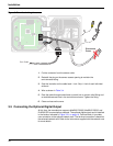
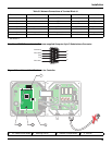
1. J1—Network connector 8. Sensor connector
2. J2—Header for optional network interface card 9. Sensor connector
3. J5—Relay A connector 10. J6—Analog output (4–20 mA) connector
4. J6—Relay B connector 11. J5—Sensor connector for hard-wiring
5. J7—Relay C connector 12. Position for network interface card
6. Fuses (F1, F2) 13. Service port
7. J8—ac Power connections 14. Sensor terminator selector/service port configuration
NCNCNC
COMCOMCOM
NO
F1
F2
NONO
RELAYCRELAYB
RELAYB
RELAYA
J1
J2
J4
NETWORK
INTERFACE
CARD
J3
J5
J6
U5
U9
S1
6
7
14
12
13
312
89
45
11 10