


16
Installation
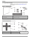
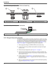
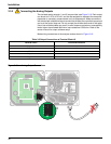
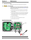
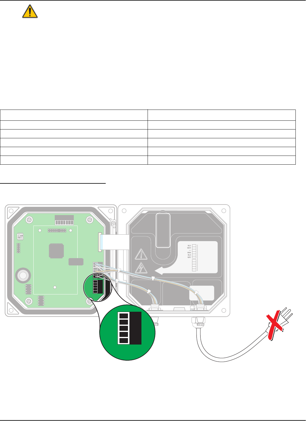
3.3.2 Connecting the Analog Outputs
Two isolated analog outputs (1 and 2) are provided, see Figure 3-18. Each output
can be set to 0–20 or 4–20 mA, and can be assigned to represent the measured
parameter or secondary measurement such as temperature. Make connections
with twisted-pair shielded wire and connect the shield at the controlled component
end or at the control loop end. Do not connect the shield at both ends of the cable.
Use of non-shielded cable may result in radio frequency emission or susceptibility
levels higher than allowed. Maximum loop resistance is 500 ohm. Refer to the
sensor manual for output software setup.
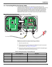
Make wiring connections at the analyzer end as shown in Figure 3-18.
Figure 3-18 Analog Output Connections
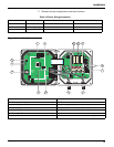
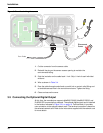
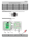
Table 3-3 Output Connections at Terminal Block J6
Recorder Wires Circuit Board Position
Output 2 + 1
Output 2 – 2
Shield 3
Output 1 + 4
Output 1 – 5
NCNCNC
COMCOMCOM
NO
F1
F2
NONO
RELAYCRELAYBRELAYA
J1
J2
J4
S1
NETWORK
INTERFACE
CARD
J3
J5
J6
U5
U9
1
1
+
DATA
+
DATA
+
OUT 2
+
OUT 2
– DATA
– OUT 2
SERVICE REQUEST
SHIELD/CHASSIS GND
+
V
+
V
+
OUT 1
+
OUT 1
GND
– OUT 1
2
2
3
3
4
4
5
5
6
PROBES
ANALOG OUTPUTS
PCB
CONNECTOR
PCB
CONNECTOR
FIELD WIRING
INSULATION MUST
BE RATED TO
80° C MINIMUM
FIELD WIRING
INSULATION MUST
BE RATED TO
80° C MINIMUM
J5J5
J6
1
2
3
4
5