


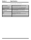
Installation
11
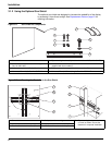
3.2 Electrical Installation
DANGER
The instrument must be installed
by qualified technical personnel
for adherence to all applicable
electrical codes.
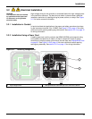
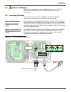
High-voltage wiring for the controller is conducted behind the high voltage barrier
in the controller enclosure. The barrier must remain in place unless a qualified
installation technician is installing wiring for power, alarms, or relays. See
Figure
3-11 for barrier removal information.
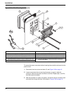
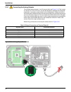
3.2.1 Installation in Conduit
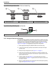
In hard-wired electrical applications, the power and safety ground service drops
for the instrument must be 18 to 12 AWG. See
Figure 3-12 on page 12 for strain
relief and conduit opening sealing plug information. See section 3.2.3 on page 12
for wiring information.
3.2.2 Installation Using a Power Cord
A sealing-type strain relief to maintain the NEMA 4X/IP66 environmental rating
and a power cord less than 3
meters (10 feet) in length with three 18-gauge
conductors (including a safety ground wire) can be used, see
Replacement Parts
on page 21. See Figure 3-12 on page 12 for strain relief and conduit opening
sealing plug assembly. See section 3.2.3 on page 12 for wiring information.
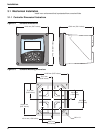
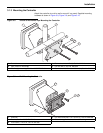
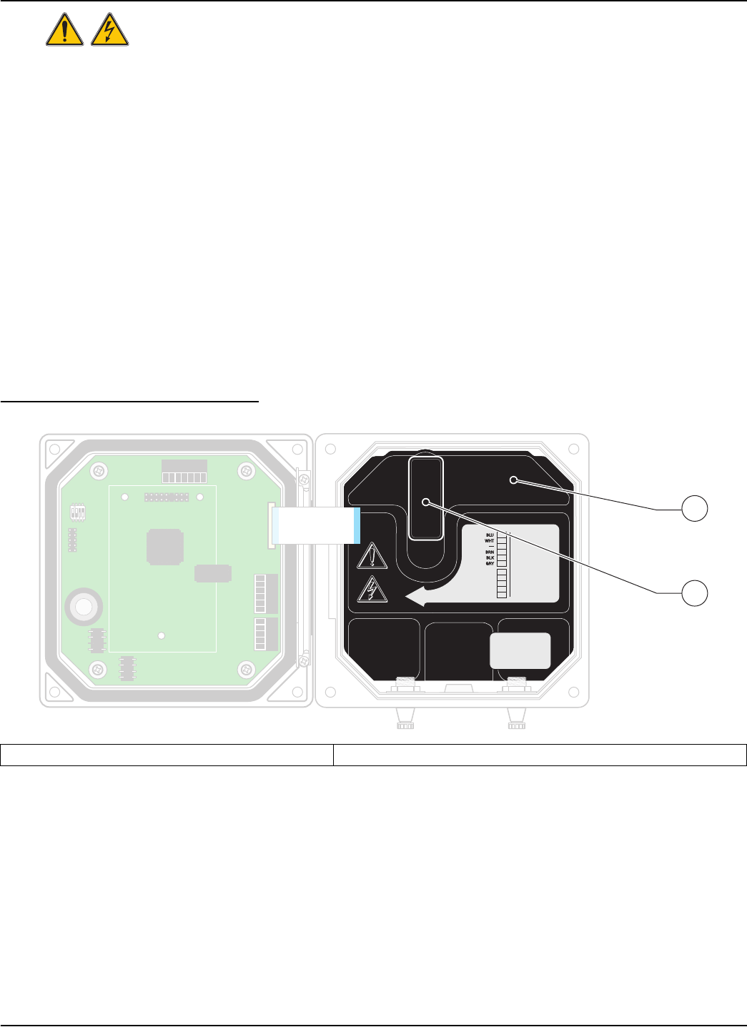
Figure 3-11 Removing Voltage Barrier
1. High voltage barrier 2. Unsnap the barrier latch then pull out to remove the barrier.
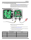
1
1
+
DATA
+
DATA
+
OUT 2
+
OUT 2
– DATA
– OUT 2
SERVICE REQUEST
SHIELD/CHASSIS GND
+
V
+
V
+
OUT 1
+
OUT 1
GND
– OUT 1
2
2
3
3
4
4
5
5
6
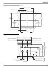
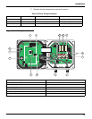
PROBES
ANALOG OUTPUTS
PCB
CONNECTOR
PCB
CONNECTOR
FIELD WIRING
INSULATION MUST
BE RATED TO
80° C MINIMUM
FIELD WIRING
INSULATION MUST
BE RATED TO
80° C MINIMUM
J1
J2
J4
NETWORK
INTERFACE
CARD
J3
J5
J6
U5
U9
S1
1
1
+
DATA
+
DATA
+
OUT 2
+
OUT 2
– DATA
– OUT 2
SERVICE REQUEST
SHIELD/CHASSIS GND
+
V
+
V
+
OUT 1
+
OUT 1
GND
– OUT 1
2
2
3
3
4
4
5
5
6
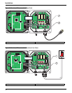
PROBES
ANALOG OUTPUTS
PCB
CONNECTOR
PCB
CONNECTOR
FIELD WIRING
INSULATION MUST
BE RATED TO
80° C MINIMUM
FIELD WIRING
INSULATION MUST
BE RATED TO
80° C MINIMUM
J1
J2
J4
NETWORK
INTERFACE
CARD
J3
J5
J6
U5
U9
S1
2
1