


36
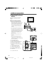
Additional preparation
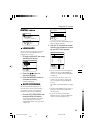
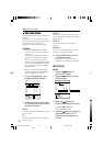
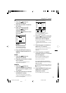
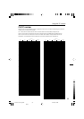
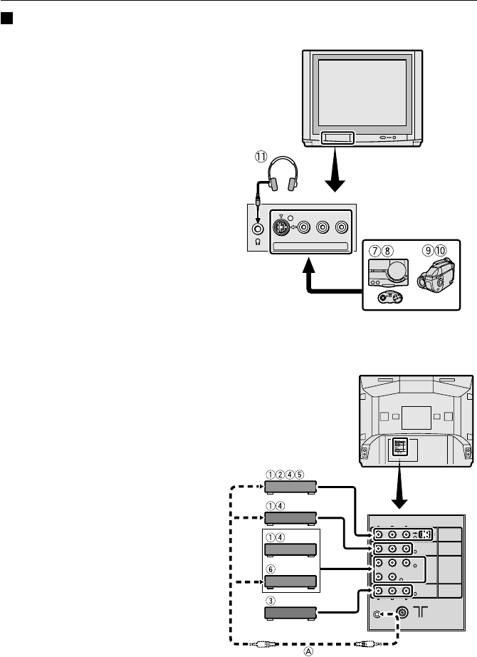
Connecting the external
devices
Connect the devices to the TV, paying
attention to the following connection
diagram.
Before connecting anything:
• Read the manuals provided with the
devices. Depending on the devices, the
connection method may differ from the
figure. In addition, the device settings
may be changed depending on the
connection method to secure proper
operation.
• Turn off all the devices including the TV.
• The "Specifications" on page 43 contains
the details of the VIDEO terminals. If you
are connecting a device not listed in the
following connection diagram, see the
"Specifications" to choose the best
VIDEO terminal.
• Note that connecting cables are not
supplied.
• When connecting devices that are
supported by AV COMPU LINK, see
"Connecting AV COMPU LINK Supported
Devices" on page 38.
1 VCR (composite signal)
2 VCR (S-VIDEO signal; Y/C)
3 VCR for recording (composite signal)
4 DVD player (composite signal)
5 DVD player (S-VIDEO signal; Y/C)
6 DVD player (component video signals;
Y/C
B
/C
R
)
7 TV game (composite signal)
8 TV game (S-VIDEO signal; Y/C)
9 Camcorder (composite signal)
0 Camcorder (S-VIDEO signal; Y/C)
- Headphones
A AV COMPU LINK cable
(Behind the cover)
S
IN (VIDEO-4)
VRL/MONO
R
RL
L/MONO
AUDIO
AUDIO
L/MONOR AUDIO
C
R
C Y/VIDEO
B
VIDEO
VIDEO-2
VIDEO
OVER
S
VIDEO-3/
COMPONENT
VIDEO-1
OUTPUT
AV COMPULINK
S
VIDEO
VIDEO-1
VIDEO-2
VIDEO-3
COMPONENT
OUTPUT
Y/VIDEOC
B
C
R
VIDEO
AV COMPU LINK
L/MONO
AUDIO
OVER
R
L/MONO
AUDIO
R
L
AUDIO
R
OVER
LCT1215-001A-H_p22-44 4/11/02, 8:59 AM36
Black