15
1
2
3
4
5
6
7
8
CNTL-1
INPUT
CNTL-2
TALLY
GND
To open-circuit
To open-circuit
To open-circuit
To
short-circuit
To
short-circuit
To short-circuit
Tally lamp
To turn off
To turn on
∗1
q
REMOTE SELECT
r
INPUT
CNTL - 1
CNTL - 2
:A B
:UNDER SCAN
:ASPECT RAT IO
:
ENTER
NOTE
NOTE
WHITE BALANCE ADJUST (white balance adjustments)
Before making these adjustments, select the color
temperature 9300K or 6500K on MENU.
REMOTE SELECT (TALLY/REMOTE-terminal settings)
Via the TALLY/REMOTE terminal, the tally lamp can be
turned on/off, or a function (selected from display
33
33
3 shown
on the right) can be operated using an external control.
INPUT setting indications and selected inputs
CNTL-1/CNTL-2 setting indications and set positions
[TALLY/REMOTE terminal functions
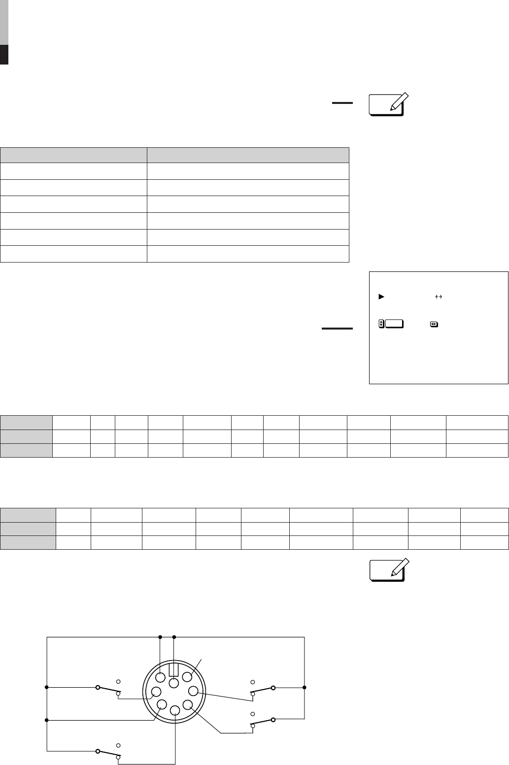
All controls via TALLY/REMOTE terminal are made by short-circuiting or open-circuiting
any pin from Pin 1 to 4 and either Pin 7 or 8 (GND each) of this terminal.
When using this terminal, be sure to short-circuit Pin 5 and either Pin 7 or 8.
SET-UP FOR MONITOR INSTALLATION (continued)
● By making white balance
adjustments on SET-UP MENU, ✻
appears to the right of the COLOR
TEMP. setting on MENU
(see page 11).
33
33
3
❉: indicates when deactivating the remote control via the TALLY/REMOTE terminal
❉: indicates when deactivating the remote control via the TALLY/REMOTE terminal
● When the TALLY/REMOTE terminal
is used, the following functions
become deactivated (except when
they are set to "NOT USE"):
- Front INPUT SELECT and EXT
SYNC switches
- Front UNDER SCAN, PULSE
CROSS, COLOR OFF and BLUE
CHECK switches
- On-screen MENU’s ASPECT RATIO
and COLOR TEMP. functions
- Remote MUTE key
● If a function is applied to both CNTL-1
and CNTL-2, CNTL-1 has priority.
∗1: Pin 6 is DC power output pin. It
outputs DC 5 V when the monitor’s
power is on. (Do not short-circuit pin 6
directly to ground.)
Adjustment (level) Function
RED DRIVE (-10,-9…0…+9, +10) Adjusts the drive level of a red signal component.
GREEN DRIVE (-10,-9…0…+9, +10) Adjusts the drive level of a green signal component.
BLUE DRIVE (-10,-9…0…+9, +10) Adjusts the drive level of a blue signal component.
RED CUTOFF (-10,-9…0…+9, +10) Sets the cut-off voltage of a red signal component.
GREEN CUTOFF (-10,-9…0…+9, +10) Sets the cut-off voltage of a green signal component.
BLUE CUTOFF (-10,-9…0…+9, +10) Sets the cut-off voltage of a blue signal component.
NOT USE UNDER SCAN PULSE CROSS COLOR OFF BLUE CHECK EXTERNAL SYNC ASPECT RATIO COLOR TEMP. AUDIO MUTE
∗ ON ON ON ON External 16-9 6500 ON
∗ OFF OFF OFF OFF Internal 4-3 9300 OFF
Setting Indication
Short-circuit
Open-circuit
NOT USE AÔB AÔY/C AÔRGB AÔCOMPO BÔY/C BÔRGB BÔCOMPO Y/CÔRGB Y/CÔCOMPO RGBÔCOMPO
∗ A A A A B B B Y/C Y/C RGB
∗ B Y/C RGB COMPO. Y/C RGB COMPO. RGB COMPO. COMPO.
Setting
Indication
Short-circuit
Open-circuit


