


6
NOTE
q
MENU
r
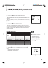
ASPECT RAT IO
F I LTER SELECT
PEAK ING
FREQ.
PEAK ING
LEVEL
AFC
COLOR
TEMP.
NTSC
SETUP
COMPO. LEVEL
q
MEMORY MODE
r
RGB
/
COMPO(SDI)
:
:4-3
:COMB
:2.6MHZ
:0dB
:NORMAL
:6500
:7.5
:BETA75
:RGB
ENTER
IN
OUT
TALLY/
REMOTE
FOCUS
IN
OUT
RGB/COMPO(SDI)
VIDEO B
SYNC
OPEN 75
OPEN 75
OPEN 75
OPEN 75
OPEN
OPEN
OPEN
VIDEO A
AUDIO
75
75
75
Y / C
B / B-Y
R / R-Y
G / Y
IN
OUT
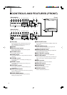
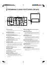
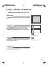
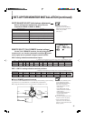
External/internal synchronization
Push the front panel EXT SYNC switch to ON, and the monitor oper-
ates to synchronize with an external sync signal input to the rear panel
SYNC IN terminal.
Push the switch again to OFF, and the monitor operates to synchro-
nize with a sync signal included in a video signal (if it includes a sync
signal) input via a video input terminal.
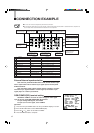
CONNECTION EXAMPLE
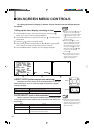
RGB/COMPO(SDI) terminal setting
Set RGB or COMPO. on screen to match the type of video signal
input to the rear panel RGB/COMPO(SDI) IN terminals.
To input analog RGB signals, set to RGB.
To input Y, B-Y or R-Y signal, set to COMPO.
Operation:
1. Press the front panel MENU button to call up the MENU display on screen.
2. Press the ▲ or ▼ button to select RGB/COMPO(SDI).
3. Press the or button to set RGB or COMPO..
4. Press the MENU button to complete.
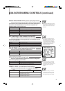
●Be sure to turn off each component’s power before connection.
●The connection shown below is only an example. Terminals and their functions differ in accordance with a component to
be connected. Also read and follow the instructions for the component.
For audio signal input from the
component connected to
RGB/COMPO(SDI) IN
For audio signal input from the
component connected to VIDEO A IN
For bridge-connected output of
@@
@@
@
For audio signal input from the
component connected to VIDEO B
IN or Y/C IN
Component that outputs a
composite video signal
Component that outputs a
composite video signal
Component that outputs Y/C signals
Component that outputs
analog RGB signals
Component that outputs
a component signal
For bridge-connected output of
~~
~~
~
For bridge-connected output of
$$
$$
$
Component that outputs
a sync signal
Remote control
component
##
##
#
33
33
3
11
11
1
22
22
2
44
44
4
77
77
7
88
88
8
~~
~~
~
!!
!!
!
@@
@@
@
%%
%%
%
$$
$$
$
==
==
=
--
--
-
00
00
0
99
99
9
55
55
5
66
66
6
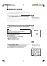
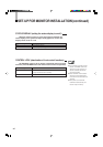
Signal(s) Terminal Function
11
11
1 Composite video VIDEO A IN Input of a composite video signal
22
22
2 Composite video VIDEO A OUT Bridge-connected output of
11
11
1
33
33
3 Composite video VIDEO B IN Input of a composite video signal
44
44
4 Composite video VIDEO B OUT Bridge-connected output of
33
33
3
55
55
5 Composite sync SYNC IN Input of an external sync signal
66
66
6 Composite sync SYNC OUT Bridge-connected output of
55
55
5
77
77
7 Y/C Y/C IN Input of Y/C signals
88
88
8 Y/C Y/C ONT Bridge-connected output of
77
77
7
99
99
9 Analogue RGB RGB/COMPO(SDI) IN Input of analogue RGB signals
00
00
0 Component RGB/COMPO(SDI) IN Input of a component signal
--
--
- Analogue RGB or component RGB/COMPO(SDI) OUT Bridge-connected output of
99
99
9 or
00
00
0
==
==
= Tally/remote control TALLY/REMOTE Input of a tally signal or remote control signal