


Masterpage:Right+
EN 13
Filename [DR-MV1SU_04Name.fm]
Page 13 February 24, 2004 12:52 pm
INDEX
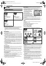
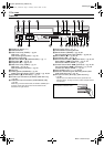
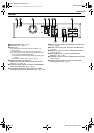
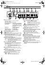
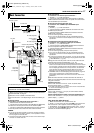
Rear View
A Region Number Label ੬ pg. 9
B AC Power Cord
੬ pg. 17
C Cooling Fan
● This prevents the temperature from rising inside the unit.
Do not remove it.
● Install the unit so as not to block the area around the fan.
● The cooling fan on the rear of the unit may be activated even if
the unit is turned off in the following cases;
— in the Automatic Satellite Program Recording standby mode
(
੬ pg. 46)
— when “AUTO CLOCK” is set to “ON” (
੬ pg. 20)
D Digital Audio Output Connectors
(DIGITAL AUDIO OUT (COAXIAL/OPTICAL)) (DVD
deck only)
੬ pg. 69, 72
E Component Video Output Connectors (COMPONENT
VIDEO OUT) (DVD deck only)
੬ pg. 17
F S-video/Video/Audio Output Connectors (S-VIDEO/
VIDEO/AUDIO OUTPUT) (DVD deck only)
੬ pg. 17, 68
G S-video Input Connector (S-VIDEO INPUT) (DVD deck
only)
੬ pg. 68
H Antenna Input Connectors (VHF/UHF IN (DVD/VCR))
੬ pg. 17
I Video/Audio Input Connectors (VIDEO/AUDIO INPUT
(L-1))
੬ pg. 68
J Video/Audio Output Connectors (VIDEO/AUDIO
OUTPUT)
੬ pg. 17, 68
K Cable Box Control Connector (CABLE BOX) (DVD deck
only)
੬ pg. 22
L Antenna Output Connectors (VHF/UHF OUT (ANT.
LOOP. OUT/TV OUT))
੬ pg. 17
1
OUTPUT
DVD/VCR VHF/UHF
OUTPUT
DVD
INPUT L-1
DVD/VCR
COAXIAL
OPTICAL
DVD DVD
DVD
IN
VCR
Y
L
R
PB
PR
DIGITAL
AUDIO OUT
COMPONENT
VIDEO OUT
VIDEO
S-VIDEO
S-VIDEO
AUDIO
VIDEO
AUDIO
PCM/
STREAM
L
R
VIDEO
AUDIO
CABLE
BOX
ANT. LOOP OUT TV OUT
L
R
OUT
J
A B C DFE
H
G
LKI
DR-MV1SU_00.book Page 13 Tuesday, February 24, 2004 12:53 PM