


11
Available signals
The following signals can be input to this monitor.
Video signals
Terminal Available signals
VIDEO IN A terminals NTSC, PAL, SECAM, PAL60, NTSC4.43, PAL-M, PAL-N, BW (50 Hz/60 Hz)
VIDEO IN B (RGB/
COMPO.) terminal
Component signals 480/60i, 576/50i, 480/60p, 576/50p, 720/60p, 720/50p, 1080/60i
(1035/60i)*, 1080/50i, 1080/24psF
RGB signals 15 kHz/50 Hz, 15 kHz/60 Hz
* Select an appropriate setting for High-Defi nition signal (see “1080/1035“ on page 23).
Computer signals (Preset)
VIDEO IN B (RGB/COMPO., DVI-D) terminals
No. Signal name
Screen resolution Horizontal
frequency
(kHz)
Vertical
frequency
(Hz)
Scan system
Input terminal
Horizontal Vertical RGB/COMPO. DVI-D
1 PC98 640 400 24.8 56.4 Non-interlace √ —
2VGA400-70 640 400 31.5 70.1 Non-interlace √ —
3VGA480-60 640 480 31.5 59.9 Non-interlace √ √
4WVGA-60 852 480 31.5 59.9 Non-interlace √ —
5VGA480-72 640 480 37.9 72.8 Non-interlace √ —
6SVGA-60 800 600 37.9 60.3 Non-interlace √ √
7XGA-60 1024 768 48.4 60.0 Non-interlace √ √
8WXGA-60 1366 768 48.4 60.0 Non-interlace √ √
9XGA-70 1024 768 56.5 70.1 Non-interlace √ —
10 XGA-75 1024 768 60.0 75.0 Non-interlace √ —
11 XGA-85 1024 768 68.7 85.0 Non-interlace √ —
12 XGA+-75 1152 864 67.5 75.0 Non-interlace √ —
13 SXGA-60 1280 1024 64.0 60.0 Non-interlace √ √
14 SXGA-75 1280 1024 80.0 75.0 Non-interlace √ —
15 UXGA-60 1600 1200 75.0 60.0 Non-interlace √ —
16 MAC13” 640 480 35.0 66.7 Non-interlace √ —
17 MAC16” 832 624 49.7 74.6 Non-interlace √ —
18 MAC19” 1024 768 60.2 74.9 Non-interlace √ —
19 MAC21” 1152 870 68.7 75.1 Non-interlace √ —
√ : Acceptable — : Not acceptable
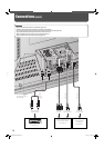
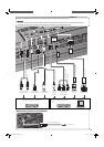
Note for VIDEO IN A (IN, Y/C IN) terminals
• When both IN terminal and Y/C IN terminal are used, the input to the Y/C IN terminal has priority.
Note for VIDEO IN B (RGB/COMPO., DVI-D) terminals
Select the correct input for Input B on the main menu (see “INPUT CONFIGURATION” on page 21).
• When RGB signals are input to the RGB/COMPO. terminal: Set “INPUT B” to “ANALOG RGB.”
• When component signals are input to the RGB/COMPO. terminal: Set “INPUT B” to “COMPONENT.”
• When using the DVI-D terminal: Set “INPUT B” to “DVI.”
Note for component signals
• The monitor is compatible only with Y on sync signals. The monitor is not compatible with composite sync (Cs) and separated sync (HD/
VD) signals.
Note for computer signals
• When a signal other than those listed above is input, part of the picture may not be displayed or an unnecessary picture may appear.
• Any signal other than those listed above may not be displayed normally although it’s frequency is within the acceptable range.
•
Depending on the connected equipment, the monitor may not be compatible with composite sync (Cs) or G on sync signals.
• When a preset mode signal is input, the signal format is displayed on the screen. For other signals, the horizontal frequency and vertical
frequency are displayed.
• The DVI-D terminal can accept only No. 3, 6, 7, 8, and No. 13 signals.
• When the No. 3 and No. 7 signals are input, set “SAMPLING MODE” to “STD” on the set-up menu (see page 29).
• When the No. 4 and No. 8 signals are input, make the following settings:
– Set “SAMPLING MODE” to “WIDE” on the set-up menu (see page 29).
– Change the aspect ratio to “FULL” (see pages 15 and 19).
– Set the video card of the personal computer to “852 x 480” (for No. 4 signal)/“1366 x 768” (for No. 8 signal).
• When No. 12 to No. 15 and No. 19 signals are input, thin lines may become obscured because their signal frequencies are higher than the
screen resolution.
• The adjustment of the screen size and position is the setting common to the No. 10 and No. 18 signals. If you use both signals by
switching them, the adjustment of either signal may not be proper.
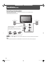
Connections
05-39_GM-H40L1G-f.indd 1105-39_GM-H40L1G-f.indd 11 05.10.6 1:13:23 PM05.10.6 1:13:23 PM