


21
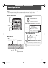
AUDIO SETTING
Item To do Setting value
SPEAKER SELECT Selects the speakers you want to use. I
NT. (Internal speakers),
EXT. (External speakers)
MUTING Turns the volume on or off . ON, OFF
AUDIO Changes the audio mode. STEREO, MONO
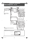
AUDIO L ch. Selects the left audio channel when the EMBEDDED AUDIO signal
is being input.
1ch += 8ch
AUDIO R ch. Selects the right audio channel when the EMBEDDED AUDIO
signal is being input.
1ch += 8ch
LEVEL METER SETTING Adjusts the audio level meter display for the EMBEDDED AUDIO signal when the HD/SD SDI or
SDI input card (option) is inserted (see “Example of the level meter display” below).
LEVEL METER ch Selects the audio channels used in the audio level meter
display. (The numbers indicate the audio channel. The
input level for the channels indicated on the left side of “:” is
displayed on the left side of the screen, and the input level for
the channels indicated on the right side of “:” is displayed on
the right side of the screen.)
OFF, 1:2, 12:34, 31:24,
123:456, 1–8
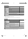
BAR TYPE Selects the color of the audio level meter display. 3COLORS (3 colors to
indicate variations in input
levels), W.100 (white), W.50
(half transparent)
BAR BRIGHTNESS Selects the brightness of the audio level meter display. HIGH, LOW
REFERENCE LEVEL Sets the standard input level. –20dB, –18dB
OVER LEVEL Sets the input level’s lower limit indicated in red for the
“3COLORS” display.
–10dB, –8dB, –6dB, –4dB,
–2dB
reset Restores the default setting for “LEVEL METER SETTING.”
reset Restores the default setting for all the items in “AUDIO SETTING.”
INPUT CONFIGURATION
Item To do Setting value
QUICK CHANGE Sets if you want to change Inputs A and B quickly. OFF, INPUT A&B
INPUT B Selects the terminal and signal type you want to use for Input B. ANALOG RGB, DVI,
COMPONENT
INPUT A Displays the terminal being used for Input A (“VIDEO (BNC)” or
“VIDEO (Y/C)”).
—
INPUT C/D/E/F Shows the status of the input card slots. When no input card is
inserted, “NO CARD” appears.
—
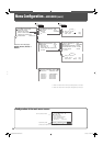
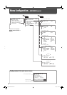
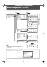
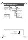
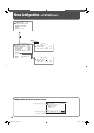
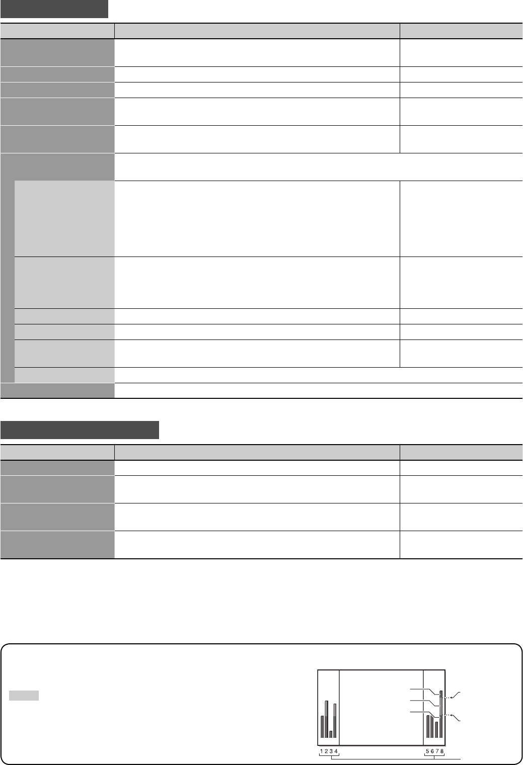
Example of the level meter display —Level indication and audio channels
Ex.: When “LEVEL METER ch” is set to “1–8” and ”BAR TYPE” is set to “3COLORS.”
NOTE
• When “BAR TYPE” is set to “W.100” or “W.50,” the standard input level set in the
“REFERENCE LEVEL” is displayed with the line indication. Input level set in “OVER
LEVEL” is not displayed.
• The audio channel bar with no signal input is displayed in white for the “3COLORS”
setting, and in gray for other settings.
OVER LEVEL
REFERENCE
LEVEL
Red
Yellow
Green
Audio channels
05-39_GM-H40L1G-f.indd 2105-39_GM-H40L1G-f.indd 21 05.10.6 1:13:36 PM05.10.6 1:13:36 PM