


4
Prep
arations
XV-C5SL/LET0227-003A/English
Preparations
Connections
Before using the unit, connect the unit to a TV and/or
amplifier.
Before making connections
• Do not connect the AC power cord until all other
connections have been made.
• Connect VIDEO OUT of the unit directly to the
video input of your TV. Connecting VIDEO OUT of
the unit to a TV via a VCR may cause a monitor
problem when playing back a copy-protected disc.
You may also have a monitor problem when
connecting the unit to an integrated TV/Video
system.
• When you use a commercial cable, be sure to
check the cable size, flexibility, and the size of the
plug, and use an equivalent one. When you do not
use the equivalent one, the cover may not be able
to attached.
• Before connection, install the unit and set the
DIRECTION switch on the rear of the unit according
to your installation (see page 6).
Connecting to a TV
The following sections A and B describe TV
connections where only a TV is connected to the unit so
that you will hear audio from the TV.
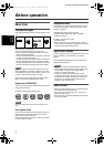
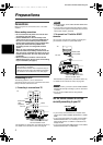
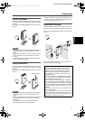
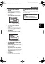
A Connecting to a conventional TV
NOTES
• In this connection, set the VIDEO SIGNAL SELECTOR
to “COMP./RGB.”
• If your TV has a monaural audio input instead of stereo,
you need to use an optional audio cable which converts
stereo audio output to monaural.
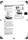
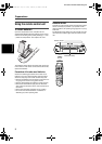
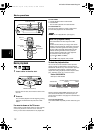
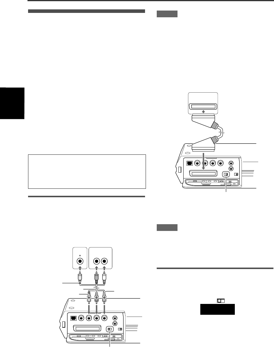
B To connect to a TV with the SCART
connector
You can enjoy using the unit by simply connecting it to
your television set with a 21-pin SCART cable.
NOTES
• In this connection, you need to set the VIDEO SIGNAL
SELECTOR correctly according to your TV. See below
for details.
• Do not connect multiple devices using multiple
connectors.
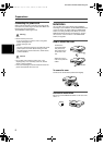
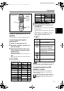
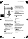
Set the VIDEO SIGNAL SELECTOR
correctly according to your TV
• If your TV only accommodates the composite video
signal, set the VIDEO SIGNAL SELECTOR to “COMP/
RGB.”
• If your TV accommodates Y/C signals, set the VIDEO
SIGNAL SELECTOR to “Y/C” so that you can enjoy
better-quality pictures. “S VIDEO” is indicated on the
display window.
• If your TV accommodates RGB signals, set the VIDEO
SIGNAL SELECTOR to “COMP./RGB.”
• In the following description, “TV” may be substituted
with “monitor” or “projector.”
• Terminal names used for other components may be
different from those used in the following description.
• For details on how to attach the cover, see page 6.
VIDEO
AUDIO
RIGHT LEFT
White
Red
Ye l l o w
Ye l l o w
Red
White
TV
The unit
This illustration is upside down. (The bottom side is up.)
For details on the connectors’ name, see page 38.
Audio/video
cable
(supplied)
VIDEO SIGNAL SELECTOR
See the “NOTES” below.
IN
TV
The unit
SCART cable
(Not supplied)
This illustration is upside down. (The bottom side is up.)
For details on the connectors’ name, see page 38.
VIDEO SIGNAL SELECTOR
See the “NOTES” below.
VIDEO SIGNAL
SELECTOR
COMP./RGB Y/C
XV-C5SL(B).book Page 4 Friday, February 21, 2003 10:59 AM