


EN 5
S400
DV IN
i.LINK IN/OUT
DIGITAL OUT
OPTICAL
PCM/DOLBY DIGITAL
REMOTE PAUSE/
AV COMPULINK
R
Y
L
P
B
/C
B
VIDEO
P
R
/C
R
S VIDEO
S VIDEO
AUDIO
IN
(L-1)
IN
(L-2)
RL
VIDEO
AUDIO
OUT
IN
S400
DV IN
i.LINK IN/OUT
DIGITAL OUT
OPTICAL
PCM/DOLBY DIGITAL
REMOTE PAUSE/
AV COMPULINK
R
Y
L
P
B
/C
B
VIDEO
P
R
/C
R
S VIDEO
S VIDEO
AUDIO
IN
(L-1)
IN
(L-2)
RL
VIDEO
AUDIO
OUT
IN
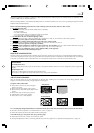
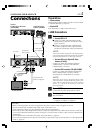
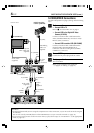
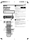
INSTALLING YOUR NEW VCR
Connections
Preparations
— Check contents
Make sure the package contains all of the accessories listed
in ‘SPECIFICATIONS’ (੬ page 59).
— Situate VCR
Place the VCR on a stable, horizontal surface.
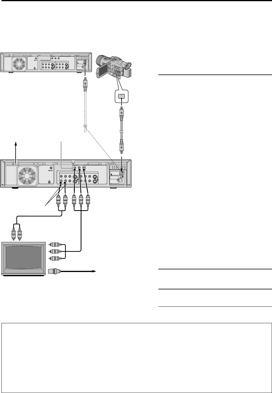
i.LINK Connections
1
Make connections
— Connect VCR to TV
1 Connect an audio cable between the VCR’s
[AUDIO OUT] connectors and the TV’s audio
input connectors.
2 Connect a component video cable between
the VCR’s Component video output terminals
and the TV’s Component video input terminals.
NOTE:
If your TV do not have Component video input terminals,
connect the S-VIDEO cable between the VCR’s [S VIDEO
OUT] terminal and the TV’s S-video input connector.
— Connect VCR to the Digital HD Video
Camera (JY-HD10)
Connect an i.LINK cable between the VCR’s
[i.LINK IN/OUT] connector and JY-HD10’s
[i.LINK IN/OUT] connector.
— Connect VCR to another VCR (SR-VD400E)
Connect an i.LINK cable between the playback
VCR’s [i.LINK IN/OUT] connector and the
recording VCR’s [i.LINK IN/OUT] connector.
NOTE:
Depending on the devices equipped with the i.LINK
connector which is connected to the VCR, picture noise
on this VCR may differ from the noise on the connected
devices. It is caused by the difference of the data
processing method.
2
Connect VCR to power source
Connect the AC power plug to the AC outlet.
3
Final preparation for use
Turn on the VCR.
● You can now perform ‘basic playback’
(੬ page 8) or ‘editing’ (੬ page 18).
AC Power
Cord
Audio Cable
(supplied)
TV (HD Ready)
Back of VCR
AC Outlet
[AUDIO OUT]
Component Video
Cable (not supplied)
NOTES:
●
When connecting VCR to TV with a component video cable, a menu screen will appear on the TV.
●
Use the commercially available i.LINK cable (4-pin, S400, below 3 m).
If the cable used is above 3 m, the operation of this VCR is not guaranteed.
●
To view the picture of 480i image format on the TV, connect the component video cable to the TV’s Y/C
B
/C
R
connectors.
If your TV uses both the Y/P
B
/P
R
and S-video connectors, connect also the S-video or video connectors between the
VCR and TV.
●
For full identification of the VCR’s rear panel, refer to the Index (
੬
page 56).
●
If you cannot see the pictures on the TV screen when you play back a tape, set “TV OUTPUT 1” to the appropriate
mode (
੬
page 38).
Aerial or cable
Component
Video Output
Another
D-VHS Digital Recorder
(SR-VD400E)
(for dubbing)
Digital HD Video
Camera (JY-HD10)
[i.LINK IN/OUT]
i.LINK cable
(not supplied)
To [i.LINK IN/OUT]