


56 EN
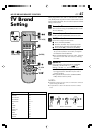
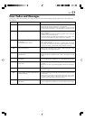
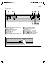
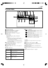
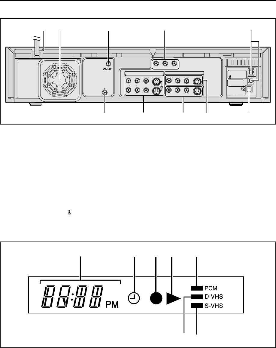
Rear panel
S400
DV IN
i.LINK IN/OUT
DIGITAL OUT
OPTICAL
PCM/DOLBY DIGITAL
REMOTE PAUSE/
AV COMPULINK
R
Y
L
P
B
/C
B
VIDEO
P
R
/C
R
S VIDEO
S VIDEO
AUDIO
IN
(L-1)
IN
(L-2)
RL
VIDEO
AUDIO
OUT
IN
09876
245
3
1
6 [REMOTE PAUSE/AV COMPULINK] terminal
● [REMOTE PAUSE] terminal : ੬ page 40
● [AV COMPULINK] terminal : ੬ page 40
7 [S VIDEO]/[AUDIO]/[VIDEO OUT] connectors :
੬ page 5, 6
8 [S VIDEO]/[AUDIO]/[VIDEO IN] connectors
[L-2]: ੬ page 6
9 [S VIDEO]/[AUDIO]/[VIDEO IN] connectors
[L-1]: ੬ page 6
0 [DIGITAL OUT OPTICAL] terminal : ੬ page 37
1 AC power cord : ੬ page 5
2 Cooling fan
● This prevents the temperature from rising
inside the VCR. Do not remove it.
● Install the VCR so as not to block the area
around the cooling fan.
3 [JLIP] terminal : ੬ page 44
4 Component video output connectors : ੬ page 5
5 [i.LINK IN/OUT], [DV IN] Connector (i.Link*)
: ੬ page 5
* i.Link refers to the IEEE1394-1995 industry specification
and extensions thereof. The logo is used for products
compliant with the i.Link standard.
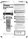
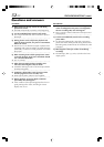
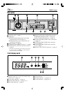
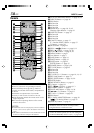
Front display panel
5 [PCM] indicator
6 [D-VHS] indicator : ੬ page 18, 21
7 [S-VHS] indicator : ੬ page 40, 41
67
234 51
1 Auxiliary input ([L-1], [L-2], [F-1] and [I-1] etc.)
Clock time : ੬ page 22
2 Timer mode indicator : ੬ page 23
3 Record mode indicator : ੬ page 22, 23
4 Play mode indicator : ੬ page 9
INDEX (cont.)