


18
Chapter 1: Connection of Equipment
Chapter 1Chapter 2Chapter 3Chapter 4Chapter 5
Chapter 6
Chapter 7
Chapter 8
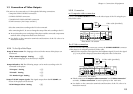
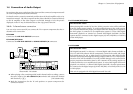
1-7 Daisy Chain Connection
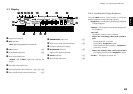
1-7-2 Connection of Video Output Terminals
Example Using S-VIDEO Connection
1
2
21
DIGITAL
DVD
CONTROL
CONTROL
MAIN
MAIN-SUB
SWITCH
SUB2
SUB1
COAXIAL
IN
OUT
OUT
INPUT OUTPUT
DAISY CHAIN
S VIDEO
VIDEO
OUTPUT
INPUT OUTPUT
MIX LINE
OPTICAL
(PCM/BIT STREAM)
INTERLACE PROGRESSIVE
COMPONENT
VIDEO
OUTPUT
1
2
21
DIGITAL
DVD
CONTROL
CONTROL
MAIN
MAIN-SUB
SWITCH
SUB2
SUB1
COAXIAL
IN
OUT
OUT
INPUT OUTPUT
DAISY CHAIN
S VIDEO
VIDEO
OUTPUT
INPUT OUTPUT
MIX LINE
OPTICAL
(PCM/BIT STREAM)
INTERLACE PROGRESSIVE
COMPONENT
VIDEO
OUTPUT
1
2
21
OUTPUT
S VIDEO
VIDEO
OUTPUT
INPUT OUTPUT
LINE
INTERLACE PROGRESSIVE
COMPONENT
VIDEO
OUTPUT
VIDEO
IN
Illust Model : DV-5900M
S-video cable (Provided)
MAIN
SUB 2
SUB 1
S-video cable (Provided)
S-video cable (Provided)
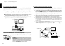
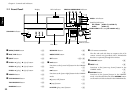
1-7-1 Setup
CONTROL
MAIN
MAIN-SUB
SWITCH
SUB2
SUB1
DAISY CHAIN
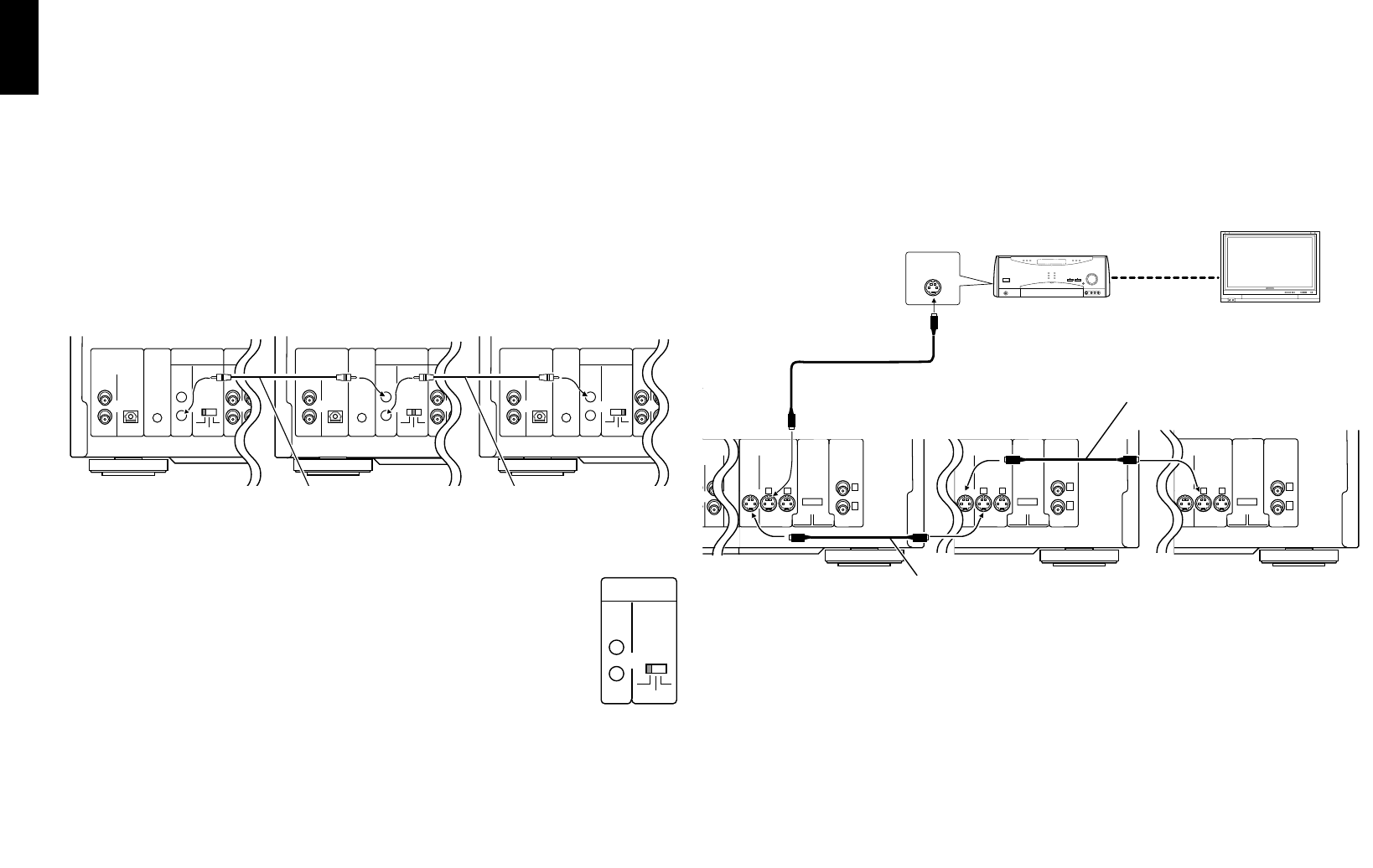
Daisy Chain Connection
Up to three changer units can be connected in series.
÷ The three units can mutually control other units.
÷ Up to 1200 discs can be played back continuously by connecting three units.
÷ Relay playback, with which discs are played in a random order is possible.
Relay playback cannot control discs in the PLUS1 to PLUS3 slots.
Random relay playback cannot play discs in the PLUS1 to PLUS3 slots.
Set the MAIN-SUB SWITCH on the rear panel of each changer unit to a
different position from other changer units.
Be sure to unplug the power cord before changing the position of the
MAIN-SUB SWITCH.
Be sure to set one of the MAIN-SUB SWITCH to “MAIN”.
It is the unit set as the “MAIN” unit that manages the discs and output the playback
signals to speakers.
When peripheral equipment (TV, AV amp, etc.) is used, connect it to the unit set as
the “MAIN” unit. “Daisy Chain Function” W
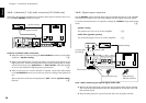
Connect the video output using either the S-VIDEO or COMPONENT VIDEO
connection.
For the connection, connect the “SUB2” unit output to the “SUB1” unit input, then
connect the “SUB1” unit output to the “MAIN” unit input as shown in the figure
below.
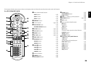
1
2
21
L
R
DIGITAL
DVD
CONTROL
CONTROL
MAIN
MAIN-SUB
SWITCH
SUB2
SUB1
COAXIAL
IN
OUT
OUT
INPUT OUTPUT FRONT SURROUND
CENTER
SUB WOOFER
DAISY CHAIN
AUDIO
COMPONENT VIDEO
S VIDEO
VIDEO
OUTPUT
6 CH. INPUT
INPUT INPUT
YCbCr YCbCr
OUTPUT OUTPUT
MIX LINE
OPTICAL
(PCM/BIT STREAM)
INTERLACE PROGRESSIVE
COMPONENT
VIDEO
OUTPUT
L
R
DIGITAL
DVD
CONTROL
CONTROL
MAIN
MAIN-SUB
SWITCH
SUB2
SUB1
COAXIAL
IN
OUT
OUT
INPUT OUTPUT FRONT SURROUND
CENTER
SUB WOOFER
DAISY CHAIN
AUDIO
COMPONENT VIDEO
6 CH. INPUT
INPUT INPUT
YCbCr YCbCr
OUTPUT
MIX LINE
OPTICAL
(PCM/BIT STREAM)
DIGITAL
DVD
CONTROL
CONTROL
MAIN
MAIN-SUB
SWITCH
SUB2
SUB1
COAXIAL
IN
OUT
OUT
INPUT OUTPUT F
R
DAISY CHAIN
MIX LINE
OPTICAL
(PCM/BIT STREAM)
System control cable
(Provided)
System control cable
(Provided)
MAIN
SUB 2
SUB 1