


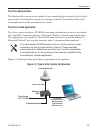
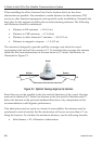
2.3 Wiring the eTrac System
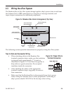
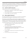
The Breakout Box of the eTrac system brings together ship’s power, data to and from
the Antenna Unit, a DB9 connection for a computer or message terminal, and
input/output connections for additional peripherals.
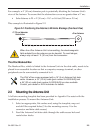
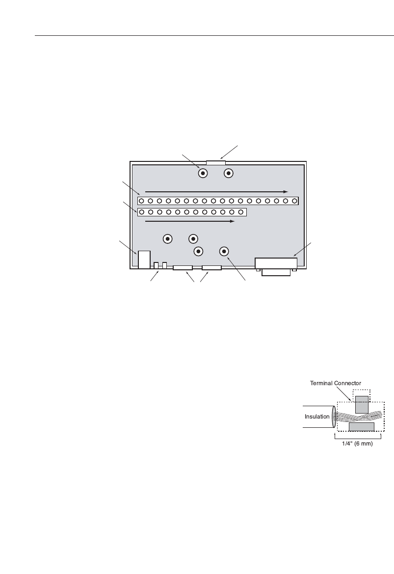
Figure 2-4: Breakout Box Interior Arrangement (Top View)
The following sections provide instructions for properly wiring the eTrac system.
Tips for Safe and Successful Wiring
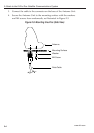
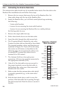
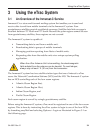
• When attaching cables to the Breakout Box
terminal connector strips, make sure the insulation
is stripped back approximately
1
⁄4" (6 mm) as
illustrated in Figure 2-5. Twist the wires gently to
help achieve a good connection. Do not pinch
insulation inside the connector.
• After attaching the cables to the appropriate
terminal connector strips, tug gently to ensure a
firm connection.
• Make sure that the Breakout Box is disconnected from ship’s power
when wiring the Antenna Unit or other peripherals. Connecting to
ship’s power should ALWAYS be the last step when wiring.
Installation
2-534-0002Rev.D
118
112
Antenna Data Cable
Access Port
Antenna Data Cable
Strain Relief Points
Power & I/O Cable
Strain Relief Points
DB9 Connecto
r
Power & I/O Cable
Access Ports
Indicator
LEDs
AC Adapter
Port
Antenna Cable
Terminal Block
(J1)
Power & I/O Cable
Terminal Block (J2)
Figure 2-5: Proper Wire to
Terminal Connection