


2.3.1 Connecting the Antenna Data Cable
The antenna data cable should now be accessible below decks. Run the cable to the
Breakout Box installation site and follow these steps.
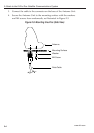
1. Remove the two screws that secure the top of the Breakout Box. Set
them aside along with the top of the Breakout Box.
2. Inside the Breakout Box, you will find a small plastic bag containing
the following:
- 3 strain relief brackets
- 6 screws for use securing the strain relief brackets
- 4 screws for use securing the Breakout Box to a stable platform
Set this bag aside for now.
3. Remove the single cable hole cap.
4. Slide a heat shrink sleeve over the data cable.
5. Insert the cable through the cable access hole.
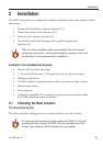
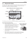
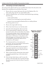
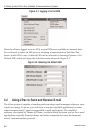
6. The J1 terminal block is labeled by wire color.
Connect the data cable as directed by these labels.
The terminal numbers, colors, and functions are
explained in Figure 2-6. If you will not be using
the remote on/off feature, as described on the
following page, do not connect the yellow wire
to terminal #13; connect the yellow wire to
terminal #6 or #14 instead.
7. The Antenna Unit has a four-pole power
connection. All four wires must be connected to
the appropriate terminals (#1-4).
8. After all of the data cable wires are secured to
the proper terminals, secure the data cable to
the Breakout Box using one of the strain relief
brackets and two screws.
9. Make certain that the antenna data cable shield
is properly grounded (e.g., to the strain relief
bracket).
10. Slide the heat shrink sleeve until it covers the
portion of the data cable that is passing through
the cable access hole. Heat the sleeve to secure it
in place.
A GuidetotheKVHeTracSatelliteCommunicationsSystem
2-6
www.kvh.com
Red
Red
Black
Black
Black/Violet
White
Black/Blue
Grey
Black/Yellow
Black/Grey
Brown
Black/Green
Yellow
Orange
Blue
Violet
Green
Black/Red
DC+
DC+
DC-
DC-
3.3 V out
GND
I/O 1
I/O 2
I/O 3
I/O 4
I/O 5
I/O 6
Remote On/Off
GND
Clear to Send
Request to Send
Receive
Transmit
1
2
3
4
5
6
7
8
9
10
11
12
13
14
15
16
17
18
Figure 2-6: J1 Terminal
Block Connectors