


18
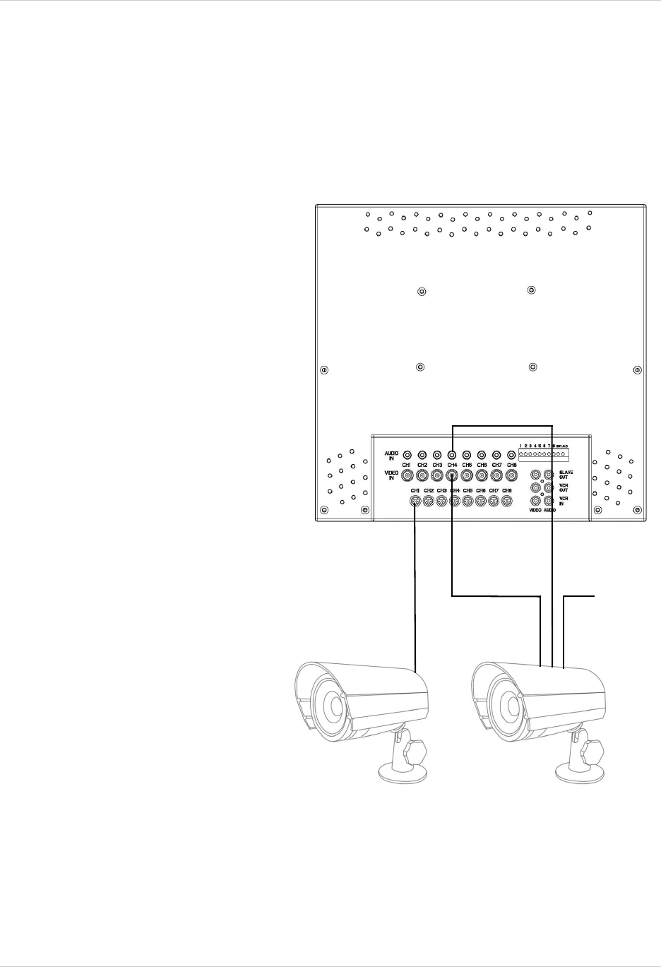
Connecting Cameras
Connecting Cameras
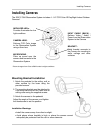
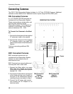
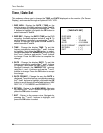
The SG17L7584 Observation System includes 4 x 1/4” Color CCD DIN Cameras. Additional
cameras can be added to the 4 additional camera inputs using the DIN or BNC ports.
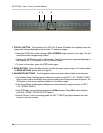
OBSERVATION SYSTEM
DIN Connected
Camera
(4 x 1/4” CCD
Included)
BNC Connected
Camera
(Optional)
Power
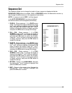
DIN Connected Cameras
4 x 1/4” COLOR CCD DIN cameras are
included with the Observation System.
These cameras have a single cable, and
receive power directly from the
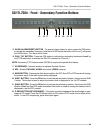
Observation System. The DIN ports are
located on to the bottom row of inputs,
and are labeled as CH1 - CH8
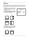
To Connect the Cameras to the Moni-
tor:
1. Connect the female end of the supplied
57’ extension’ cable to the camera
2. Connect the male end of the supplied
57’ extension cable to an open DIN
channel on the back of the Observation
System
Continue connecting additional DIN
cameras.
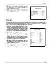
BNC Connected Cameras
BNC connected cameras are not
included with the Observation System,
however can be ordered online at
www.lorexcctv.com
BNC Cameras have several cables and
receive power from a wall outlet
1. Connect the Video cable to an open
BNC Video Port (middle row of ports)
on the back of the Observation System
labeled CH1 - CH8
2. Connect the Audio cable to correspond
to the Audio port (top row of ports) on
the back of the Observation System
matching the port connected in step 1
3. Connect the AC power and camera ,
and connect the AC Adapter to an
electrical outlet