


13EN 13EN
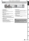
Recording Playback EditingIntroduction
Connections
Basic Setup Function Setup Others
Español
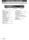
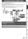
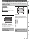
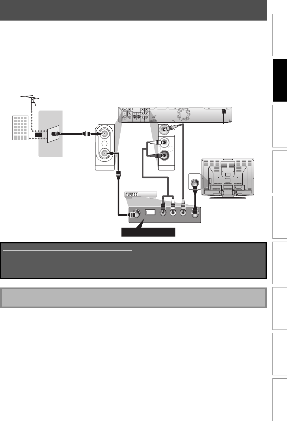
RF MODULATOR CONNECTION
rear of your TV
rear of your
RF modulator
AUDIO IN TO TVANT. IN
LR
CHANNEL
43
VIDEO IN
ANT. IN
Set channel 3 or 4
VIDEO
IN
AUDIO IN
(
E1
)
S-VIDEO
AUDIO OUT
COMPONENT
VIDEO OUT
IN OUT
L
R
L
R
IN
Y
P
B/CB
PR/CR
OUT
rear of this unit
VIDEO
OUT
R
L
AUDIO OUT
IN
OUT
ANTENNA
RF coaxial cable
RF coaxial cable
VHF / UHF
antenna
RF coaxial cable
cable TV
company
or
RCA video
cable
RCA audio cable
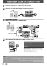
If your TV has antenna in jack only, it is still possible to connect this unit to your TV by using a stereo audio/video RF
modulator. In this case, follow the instructions below.
1) Disconnect the power cords of the devices from the AC outlet.
2) Make the connection as illustrated below.
3) Set your RF modulator’s channel 3/4 switch to either 3 or 4, whichever the TV channel is least used in your area.
If your RF modulator has a modulator/antenna switch, set it according to the manual supplied with the RF
modulator.
4) Plug in the power cords of the devices to the AC outlet.
5) Turn on your TV and choose the same channel as you set the RF modulator’s channel 3/4 switch to.
For more details, follow the manual supplied with the RF modulator.
Note
• The quality of picture may become poor if this unit is connected to an RF modulator.
Supplied cables used in this connection are as follows:
• RF coaxial cable x 1
• RCA audio cable (L/R) x 1
• RCA video cable x 1
Please purchase the rest of the necessary cables at your local store.