9
ENGLISH
11 DIGITAL OPTICAL IN
High Quality recordings can be made onto the Hard Disk of
the Music Server using an optical connection from a
suitable device (such as Minidisc or DAT).
12 DIGITAL OPTICAL OUT
The audio output can be transmitted in the form of light
through an optical fibre cable and photocoupler. The optical
signal transmission features low signal loss due to cables
and complete isolation of the ground loop so that a very
high quality output can be produced without any digital
noise. The audio output of the Digital Out connector is the
same as the audio output of the Analogue Audio Out 1
connector.
Connection method
Connect this jack to a D/A convertor, digital sound
processor or an amplifier equipped with a Digital Optical
input jack. Remove the caps from the Digital Optical Out
jack and the optical input jack of the connected component
and connect the two jacks through an optical fibre cable.
13 VIDEO OUT 2,3,4
Additional composite outputs to allow up to 4 televisions to
be connected to the Music Server. All 4 composite outputs
display the same TV User interface.
14 DIGITAL AUDIO OUT - COAXIAL
By connecting this jack to a digital audio component (D/A
convertor, digital sound processor etc.), digital signals from
the Music Server can be transmitted directly from the
system without first being converted to analogue. The
audio output of the Digital Out connector is the same as
the audio output of the Analogue Audio Out 1 connector.
15 DIGITAL AUDIO IN - COAXIAL
High Quality recordings can be made onto the Hard Disk of
the Music Server using a coaxial connection from a suitable
device (such as Minidisc or DAT).
16 ANALOGUE AUDIO IN
Analogue sources (such as cassette or vinyl LP) may be
recorded onto the Hard Disk of the Music Server using this
connection.
17 ANALOGUE AUDIO OUT 2,3,4
The DH9300 Music Server is a multiroom device allowing
you to listen to different music in up to 4 different rooms all
at the same time. Each analogue output should be
connected to the input jacks of a pre-amplifier. For more
information see the chapter called Using your Music
Server in a multiroom system p.27.
18 ANALOGUE OUT 1
See 17.
19 REMOTE IN
The Remote In connection allows remote control
information to be carried from remote rooms directly into
the Music Server. The Remote In connection number is
linked to the default output to be controlled; for instance
remote control information received at Remote In 3 will
control analogue output 3 of the Music Server by default.
For more information see the chapter called Using your
Music Server in a multiroom system p.27.
20 MAINS
Connect the supplied mains lead to this connector to
provide power to the unit.
USING THE REMOTE CONTROL
The remote control supplied with the Music Server is a
“Universal” remote control. This means that other devices,
such as a television or amplifier, may be controlled using
this remote control. When you have selected to control the
television the TV device button will light up each time you
press a button - similarly when the Music Server is selected
the HDD Audio button will light and when the Amp is
selected the Amp button will light.
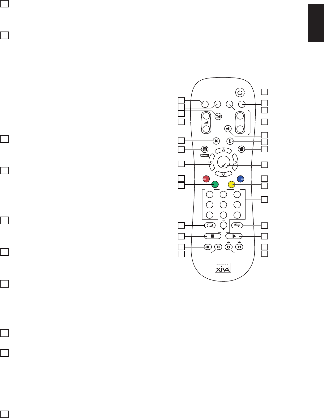
The following diagram explains the function of the keys on
your Music Server remote control:
2
3
7
8
10
13
14
16
18
22
23
25
28
27
26
24
21
20
19
17
15
12
11
9
6
5
4
1
1
3
2
0
5
jkl
6
mno
9
wxyz
4
ghi
7
pqrs
8
tuv
DELETE
TOP
CAPS.
+
_
+
_
Mute
Output
Select
Home
Album
Artist
Genre
Playlist
Default o/p
AV
-/--
TV
HDD
Audio
Amp
Disc
Standby
Ch.
-/().@*
abc
def
1. LSTANDBY button
Places the Music Server in/out of standby or off mode.
2. HDD Audio button
Selects the Music Server as the device to be controlled.
3. TV button
Selects the TV as the device to be controlled. For more
information on configuring this remote to control your
television see the chapter called Configuring your remote
to control other devices p.11.
4. DEFAULT O/P button
Resets the TV user interface to controlling the default
output for the room where you are located (indicated by the
Remote In receiver connection). For more information on
multiroom use of the Music Server see the chapter called
Using your Music Server in a multiroom system p.27. If
the TV device is selected this button will show/hide the on-
screen clock.
5. AMP button
Selects the Amp as the device to be controlled. For more
information on configuring this remote to control your
amplifier see the chapter called Configuring your remote
to control other devices p.11.


