70
Using the Video and Audio Input Jacks
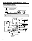
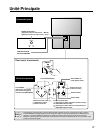
■ Connecting video equipment for video playback
• When the television is connected to video equipment as shown below, the material being played back on the
video equipment can be seen on the television screen.
Connecting a video device equipped with a video output terminal
IN 2
L-AUDIO-R
VIDEO
S-VIDEO
or
To AUDIO OUTPUT
To VIDEO OUTPUT
To S-VIDEO OUTPUT
(Front terminals of Rear Projection TV)
Signal
TV GAME
CAMCORDER
VIDEO EQUIPMENTS
ANT-A
OUT
ANT/CABLE 75
ANT-B
HD INPUT IN 3
(USE FOR HDTV SIGNAL ONLY)
COMPONENT
CENTER IN
R AUDIO L
R AUDIO L
R AUDIO L
VIDEO
VIDEO
MONITOR OUT
(EXCEPT FOR HD AND
COMPONENT SIGNALS)
S-VIDEO
Y
IN 1
IN 1 IN 3
IN 3
IN 4
IN 5
VAO
P
B
P
R
Fasten with the screws
located at both ends.
(To output terminals of DTV)
Video Equipment
Signal
Color Difference
Output Jack (Component )
To AUDIO OUTPUT (L)
To AUDIO OUTPUT (R)
Signal
To AUDIO OUTPUT (L)
To AUDIO OUTPUT (R)
To VIDEO OUTPUT
Signal
Signal
To AUDIO
OUTPUT (L/R)
To VIDEO OUTPUT
TO S-VIDEO OUTPUT
has an S-VIDEO output terminal).
(When your video equipment
T
o AUDIO
OUTPUT (L/R)
Signal
Signal
(Rear terminals of Rear Projection TV)
To HD INPUT
CENTER
OUT
Note
• The S-VIDEO INPUT terminals offer a higher quality image by accepting the image signal separated into color
and brightness signals.
• S-VIDEO INPUT terminals are for video signals only. The audio signals are connected to either IN 1 or IN 3
AUDIO terminals (left and right).
When noise or distortion appears on TV
caused by connecting a video game
machine, select the other setting of the
DDFC mode (See page 58).


