


3. TV Connections 27
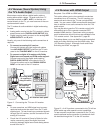
A/V Receiver (Sound System) Using
the TV’s Audio Output
Most setups require either a digital audio cable or
analog stereo audio cables. To send audio from TV
channels received on
ANT 1
,
ANT 2
, or devices con-
nected directly to the TV, you must use one of the con-
nections shown below.
The TV makes all audio available in digital and analog
formats:
Analog audio coming into the TV is output in digital •
stereo format on the
DIGITAL AUDIO OUTPUT
jack.
Digital incoming audio is output on the analog •
AVR
AUDIO OUTPUT L
and
R
jacks.
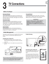
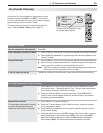
Usually, only one of the following audio connections is
required.
To connect an analog A/V receiver•
Connect left (white) and right (red) audio cables
from
AVR AUDIO OUTPUT L
and
R
on the TV main
panel to the
TV AUDIO INPUT
on the A/V receiver.
To connect a digital A/V receiver with • Dolby
Digital surround sound and PCM audio support:
Connect one end of the digital audio cable to
DIGITAL AUDIO OUTPUT
on the back of the TV.
Connect the other end to the
COAXIAL DIGITAL
INPUT
on the back of the A/V receiver.
2
1
IR-
Output / External
Controller Input
S-VIDEO
VIDEO
AUDIO
L
R
INPUT3
INPUT2 INPUT1
L
R
AVR AUDIO
OUTPUT
AUDIO
L
R
Pb
Y
Y / VIDEO
Pr
ANT2/AUX
ANT1/MAIN
DIGITAL
AUDIO
OUTPUT
NetCommand
) i 0 8 0 1 / p 0 2 7 / p 0 8 4 / i 0 8 4 (
AUDIO
R
DVI/PC
L
DIGITAL
AUDIO
OUTPUT
L
R
AVR AUDIO
OUTPUT
L
R
AVR AUDIO
OUTPUT
OUTPUT
OPTICAL
INPUT
COAXIAL
INPUT
COAXIAL
INPUT
DIGITAL
AUDIO
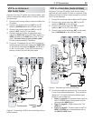
Digital coaxial cable
(for connecting a
digital A/V receiver)
Stereo analog cables
(for connecting an
analog A/V receiver)
A/V receiver back panel
Figure 11. Connecting the TV to an A/V receiver
Note:
On rare occasions, an HDMI signal may be copy-•
restricted and cannot be output from the TV as a
digital signal. To hear these copy-protected signals
through the A/V receiver, use the connection for an
analog A/V receiver.
Check the A/V receiver’s Owner’s Guide for infor-•
mation concerning use of the digital input and
switching between digital sound and analog stereo
sound from the TV.
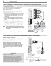
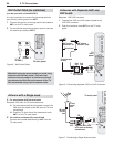
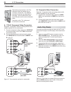
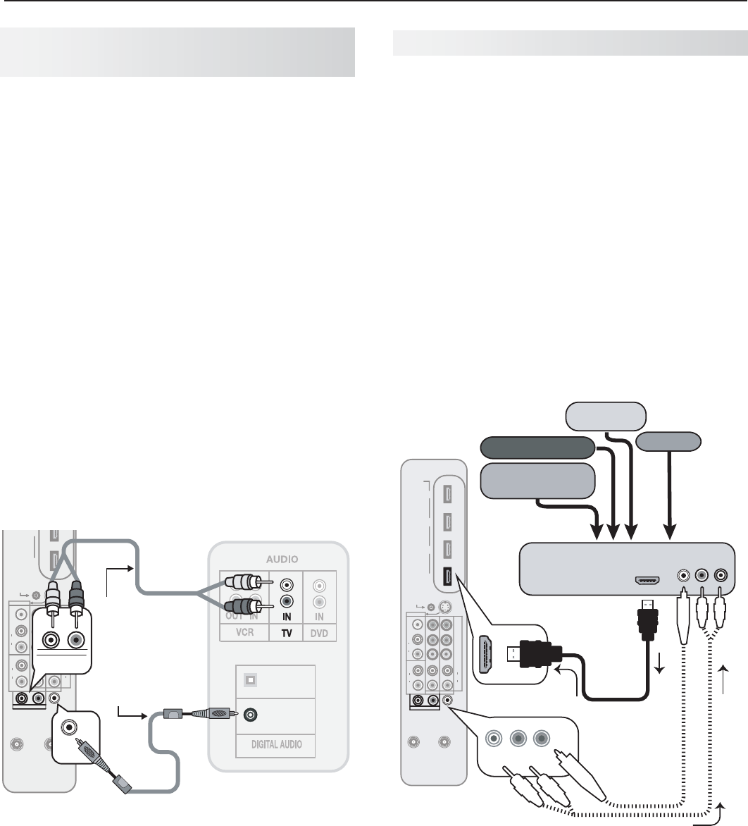
A/V Receiver with HDMI Output
Required: One HDMI-to-HDMI cable
This option allows you to view content from devices
connected to an A/V receiver. The A/V receiver can
send audio and video to the TV over a single HDMI
cable. You can use an HDMI connection as described
here in addition to an audio connection from the TV’s
audio output.
You may be able to use the TV’s remote control (with
slide switch set to
TV
) to operate connected CEC-
enabled HDMI devices. Experiment with your equip-
ment to determine which functions are available to the
TV’s remote control. See Appendix E, page 80.
This setup allows you to use NetCommand-controlled
audio and video switching over the HDMI cable. See
“A/V Receiver Control: Automatic Audio and Video
Switching via HDMI” on page 63.
HDMI
4
3
2
1
IR-
Output / External
Controller Input
S-VIDEO
VIDEO
AUDIO
L
R
INPUT3
INPUT2 INPUT1
L
R
AVR AUDIO
OUTPUT
AUDIO
L
R
Pb
Y
Y / VIDEO
Pr
ANT2/AUX
ANT1/MAIN
DIGITAL
AUDIO
OUTPUT
NetCommand
) i 0 8 0 1 / p 0 2 7 / p 0 8 4 / i 0 8 4 (
AUDIO
R
DVI/PC
L
DIGITAL
AUDIO
OUTPUT
L
R
AVR AUDIO
OUTPUT
DIGITAL
AUDIO
OUTPUT
L
R
AVR AUDIO
OUTPUT
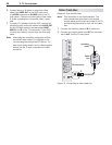
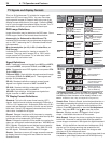
HDMI OUT
A/V receiver with
HDMI output
Audio from TV to A/V Receiver
High-definition
DVD player
DVD player
Cable box
VCR
TV main
panel
HDMI
cable
(Video to TV)
Optional
analog or
digital audio
connection
Figure 12. An A/V receiver connected to the TV with an
HDMI cable may offer special control capabilities.
To hear sound from devices connected to the TV only,
use the optional audio connection to send audio from
the devices through the TV to the A/V receiver..