131
FX3S Series Programmable Controllers
User's Manual - Hardware Edition
11
Built-in Analog
12
Output Wiring
13
Wiring for
Various Uses
14
Test Run,
Maintenance,
Troubleshooting
15
Other Extension
Units and
Options
16
Display Module
(FX
3S
-5DM)
17
Memory
Cassette
A
Special Devices
(M8000-, D8000-)
B
Instruction List
C
Discontinued
models
14 Test Operation, Adjustment, Maintenance and Troubleshooting
14.4 Maintenance and Periodic Inspection
14.4 Maintenance and Periodic Inspection
This PLC does not incorporate consumable parts that are factors in the reduction of service life.
However, the output relays (points of contact) have a limited life expectancy.
14.4.1 Periodic inspection
Check the following points.
• Check that the temperature in the panel is not abnormally increased by other heat generating bodies or
direct sunlight.
• Check that dust or conductive dust has not entered the panel.
• Check for loosening of wiring and other abnormalities.
14.4.2 Maintenance - product life of relay contacts
The product life of relay contacts varies considerably depending on the load type used. Take care that loads
generating reverse electromotive force or rush current may cause poor contact or deposition of contacts
which may lead to considerable reduction of the contact product life.
1. Inductive load
Inductive loads generate large reverse electromotive force between contacts at shutdown, which may cause
arcing. At a fixed current consumption, as the power factor (phase between current and voltage) gets smaller,
the arc energy gets larger.
The standard life of contacts used for Inductive loads, such as contactors and solenoid valves, is 500,000
operations at 20 VA.
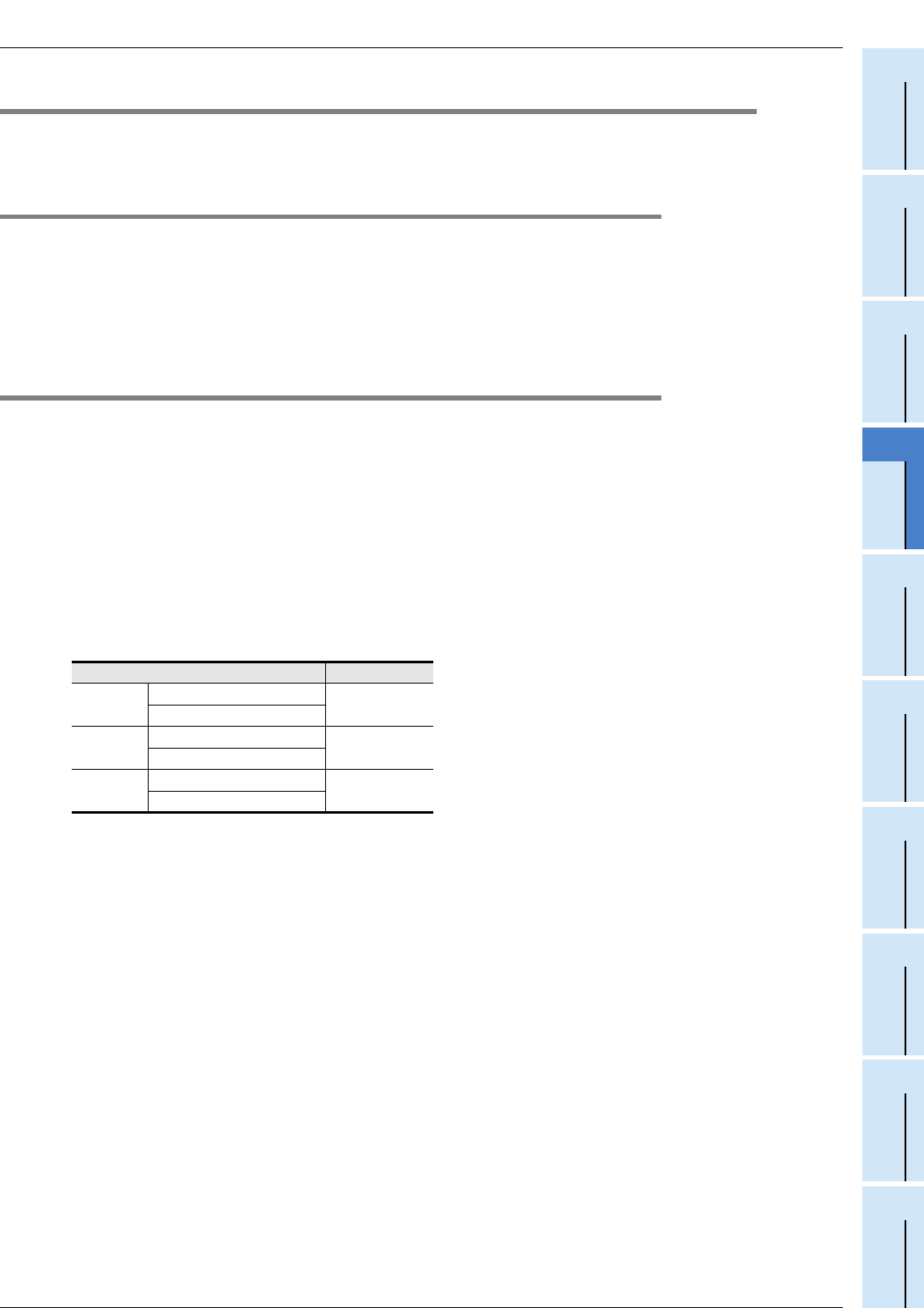
The following table shows the approximate life of a relay based on the results of an operation life test.
Test condition: 1 sec. ON / 1 sec. OFF
The product life of relay contacts becomes considerably shorter than the above conditions when the rush
overcurrent is shut down.
Please refer to the following measures regarding the inductive load.
Refer to Subsection 12.1.3-2.
Some types of inductive loads generate rush current 5 to 15 times the stationary current at activation.
Make sure that the rush current does not exceed the current corresponding to the maximum specified
resistance load.
2. Lamp load
Lamp loads generally generate rush current 10 to 15 times the stationary current. Make sure that the rush
current does not exceed the current corresponding to the maximum specified resistance load.
3. Capacitive load
Capacitive loads can generate rush current 20 to 40 times the stationary current. Make sure that the rush
current does not exceed the current corresponding to the maximum specified resistance load. Capacitive
loads such as capacitors may be present in electronic circuit loads including inverters.
* About the maximum load specifications of the resistance load, refer to the specification for each model.
Refer to Subsection 4.1.1.
Load capacity Contact life
20 VA
0.2 A/100 V AC
3,000,000 times
0.1 A/200 V AC
35 VA
0.35 A/100 V AC
1,000,000 times
0.17 A/200 V AC
80 VA
0.8 A/100 V AC
200,000 times
0.4 A/200 V AC


