


3 - 5 3 - 5
MELSEC-Q
3 SPECIFICATIONS
3.3 I/O Signals for the CPU Module
3.3.1 List of I/O signals
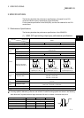
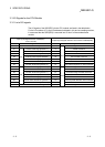
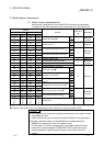
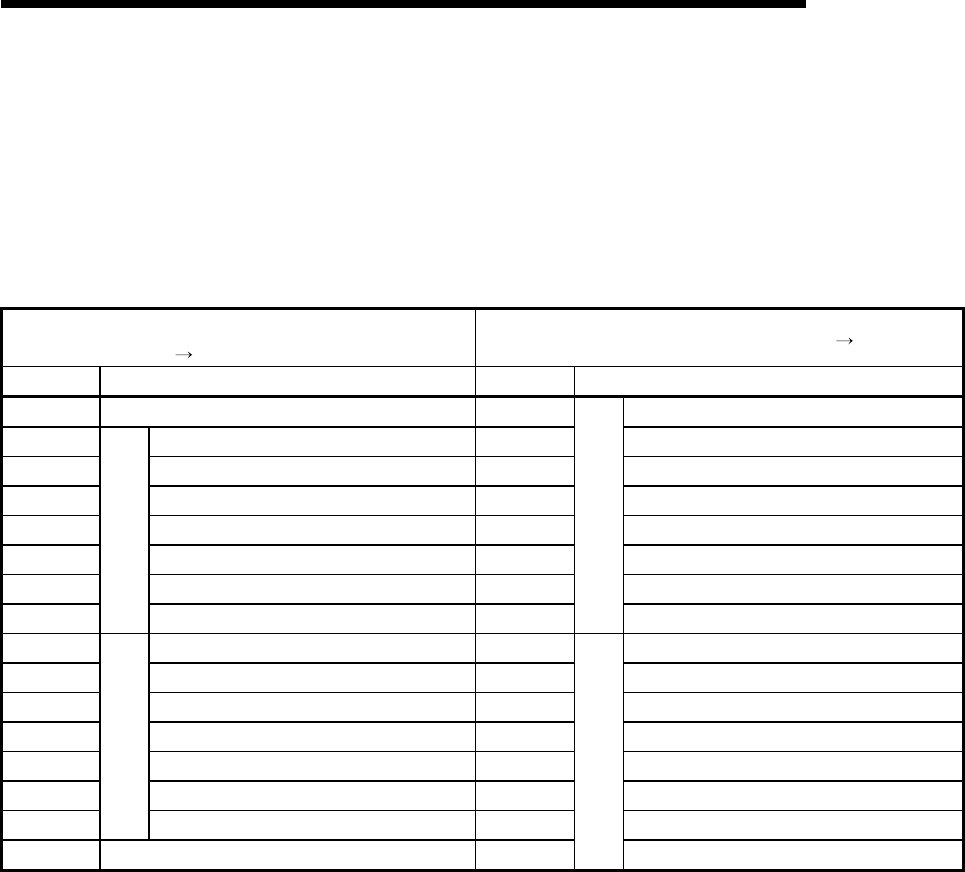
The I/O signals of the QD62(E/D) for the CPU module are listed in the table below.
For the I/O numbers (X/Y) and I/O addresses indicated in this and succeeding sections,
it is assumed that the QD62(E/D) is mounted into I/O slot 0 of the standard base
module.
Input signal (Signal direction: QD62(E/D)
CPU module)
Output signal (Signal direction: CPU module
QD62(E/D))
Device No. Signal name Device No. Signal name
X0 Module ready Y0 Coincidence signal No. 1 reset command
X1 Counter value large (point No. 1) Y1 Preset command
X2 Counter value coincidence (point No. 1) Y2 Coincidence signal enable command
X3 Counter value small (point No. 1) Y3 Down count command
X4 External preset request detection Y4 Count enable command
X5 Counter value large (point No. 2) Y5 External preset detection reset command
X6 Counter value coincidence (point No. 2) Y6 Counter function selection start command
X7
CH1
Counter value small (point No. 2) Y7
CH1
Coincidence signal No. 2 reset command
X8 Counter value large (point No. 1) Y8 Coincidence signal No. 1 reset command
X9 Counter value coincidence (point No. 1) Y9 Preset command
XA Counter value small (point No. 1) YA Coincidence signal enable command
XB External preset request detection YB Down count command
XC Counter value large (point No. 2) YC Count enable command
XD Counter value coincidence (point No. 2) YD External preset detection reset command
XE
CH2
Counter value small (point No. 2) YE Counter function selection start command
XF Fuse broken detection flag YF
CH2
Coincidence signal No. 2 reset command