


6
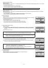
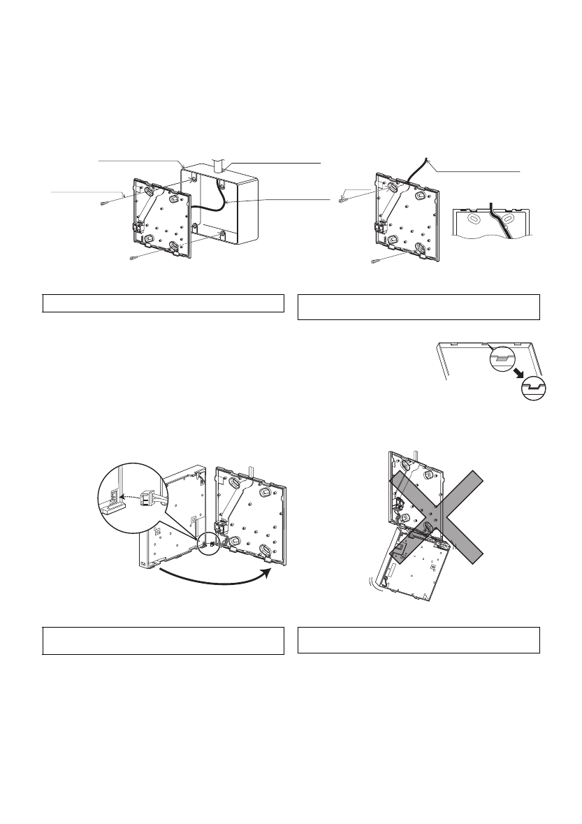
5 Install the bottom case.
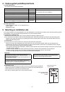
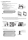
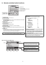
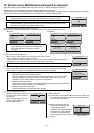
■ Installation using a switch box
Secure at least two corners of the switch box with screws.
■ Direct wall installation
Thread the cable through the groove.
Secure at least two corners of the remote controller with screws.
Be sure to secure top-left and bottom-right corners of the remote controller (viewed from the front) to prevent it from lifting.
(Use molly anchor etc.)
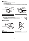
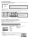
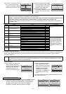
7 Route the wire to the top case.
Connect the connector on the bottom case to the connector on the top case.
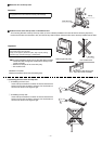
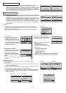
6 Cut out the cable access hole.
■ Direct wall installation (when running the cable along the wall)
Cut out the thin-wall part on the cover (indicated with diagonal lines in the right figure)
with a knife or a nipper.
Thread the cable from the groove behind the bottom case through this access hole.
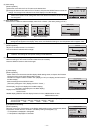
■ Installation using a switch box ■ Direct wall installation
Seal the cable access
hole with putty.
Double switch box
Roundhead cross
slot screws
Remote controller
cable
Wood
screw
Remote controller
cable
Thread the cable
through the groove.
Refer to 1.
Refer to 4.
Refer to 4.
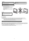
To avoid damage to the controller, do not overtighten the screws. To avoid damage to the controller, do not make holes on the controller
cover.
Important
Securely connect the
connectors.
To prevent malfunctions, do not remove the protective film or the
circuit board from the casing.
To prevent cable breakage and malfunctions, do not hang the top
controller casing hang by the cable.
Important
WT05950X01_1_GB_A5.fm Page 6 Tuesday, September 28, 2010 11:19 AM