


14
15
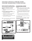
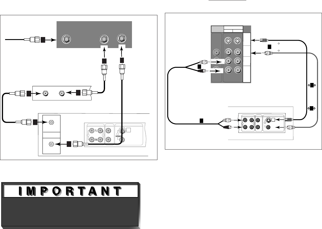
Connecting an Antenna to a Cable Box and VCR,
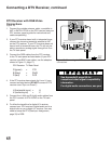
Connecting Composite Video or S-Video with Audio
AUDIOOUT
AUDIOIN
VIDEOOUT
(Y/C)
MONITOR
1
L
R
L
R
1
2
Cablebox orVCR backpanel
Attach
only
one
cable
type
1
Attachonly
onecabletype
1
2
2
White
Red
White
Red
TV back panel
(section detail)
INPUT
2
1
AUDIO-
RIGHT
AUDIO-
LEFT/
(MONO)
VIDEO
S-VIDEO
M
O
N
I
T
O
R
OUT
(Recommended if available)
1
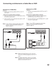
Figure 6. Connecting Composite Video and Audio.
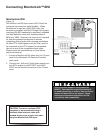
Figure 5. Connecting the VCR with cable box.
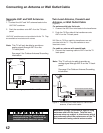
Additional connection cables are not
provided with the TV. They should be
available at most electronic stores.
Antenna to Cable Box and VCR
(Figure 5)
1. Connect the incoming cable to ANT-A on the TV
back panel.
Connect three coaxial cables as follows:
2. One from LOOP-OUT on the TV back panel to IN
on the back of the cable box.
3. One from OUT on the back of the cable box to
ANTENNA IN on the VCR back panel.
4. One from ANTENNA OUT on the VCR back panel
to ANT-B on the TV back panel.
Note: For best performance, connect the audio as
shown in Figure 6, page 14.
Contact your local cable or satellite provider or
refer to the cable box or satellite Owner’s Guide for
instructions on optimal connections to this TV.
Composite Video or S-Video
(Recommended) with Audio
(Figure 6)
1. Connect a video or an S-Video cable from VIDEO
OUT on the VCR back panel to VIDEO or S-VIDEO,
INPUT-1 or INPUT-2 on the TV back panel.
2. Connect a set of audio cables from AUDIO OUT on
the VCR back panel to AUDIO INPUT-1 or INPUT-2
on the TV back panel, matching the input used in
step 1.
• The red cable connects to the R (right) channel
• The white cable connects to the L (left) channel
If your VCR is mono (non-stereo), connect only
the white (left) cable.
You may connect to the S-VIDEO or VIDEO
terminal but not to both.