


18
19
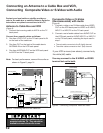
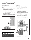
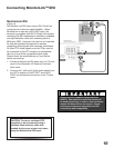
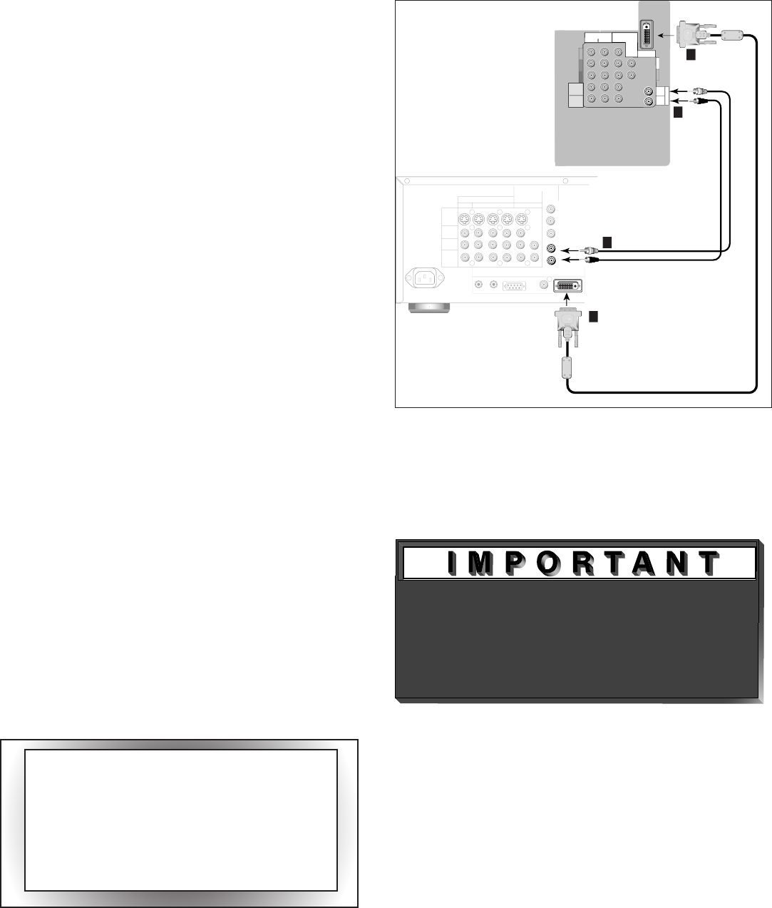
Connecting MonitorLink™/DVI
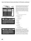
Figure 14. Connecting MonitorLink
MonitorLink/DVI
(Figure 14)
The Monitor Link/DVI input uses a DVI-I Dual Link
connector for maximum cable flexibility. When
MonitorLink is used as a DVI-HDCP input, the
terminal is compliant with DVI-D Single Link signals
matching EIA-861 standards for standard, extended
and high definition video with scanning rates of
480p and 1080i. However, this input is not intended
for use with personal computers or devices
outputting video signals with computer resolutions.
All other DTV video signals, such as 720p, need to
be converted by the DTV receiver (or compatible
device) to one of the compatible signal types.
Please check the specifications on your device
before connecting.
1.
Connect a MonitorLink/DVI cable from the TV back
panel to the Mitsubishi HD Receiver/Controller
back panel.
2.
Connect the L (left) and R (right) audio cables from
the HDTV receiver to AUDIO LEFT and AUDIO
RIGHT on the MonitorLink section of the TV back
panel.
COMPONENT
480i/480P/1080i
2
1
Y
Pr
Pb
AUDIO-
RIGHT
LEFT/
(
M
O
N
O
)
AUDIO-
V
H
DTV(YPbPr/GBRHV)
480i/480P/1080i
MONITORLINK
TM
/DVI
AUDIO-
LEFT/
(MONO)
AUDIO-
RIGHT
DVI
1
1
OUTPUTS
TO
DISPLAY
1
2
3 4
MONITOR
PIP
INPUT
TO
AVRECEIVER
A
C
I
N
DIGITALAUDIO
OUTPUT
MonitorLink
TM
/DVI
MonitorLink
TM
CONTROL/RS-232
IROUTPUT
NetCommand
R
S-VIDEO
VIDEO
AUDIO
LEFT
AUDIO
RIGHT
White
Red
MitsubishiHD-5000
receiver/controller back panel
2
White
Red
2
ferrite
core
ferrite
core
TV back panel
(section detail)
CAUTION: To assure continued FCC
compliance, we recommend using a
shielded video interface cable with
bonded ferrite cores at each end, when
using the MonitorLink/DVI input.
This connection supports copy protection
(HDCP). Some devices require connecting to
an analog input first, in order to view on-screen
menus and select DVI as the output. Please
review your equipment instructions for DVI
connectivity and compatibility.