


14
15
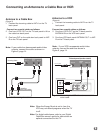
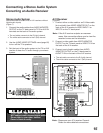
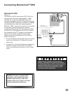
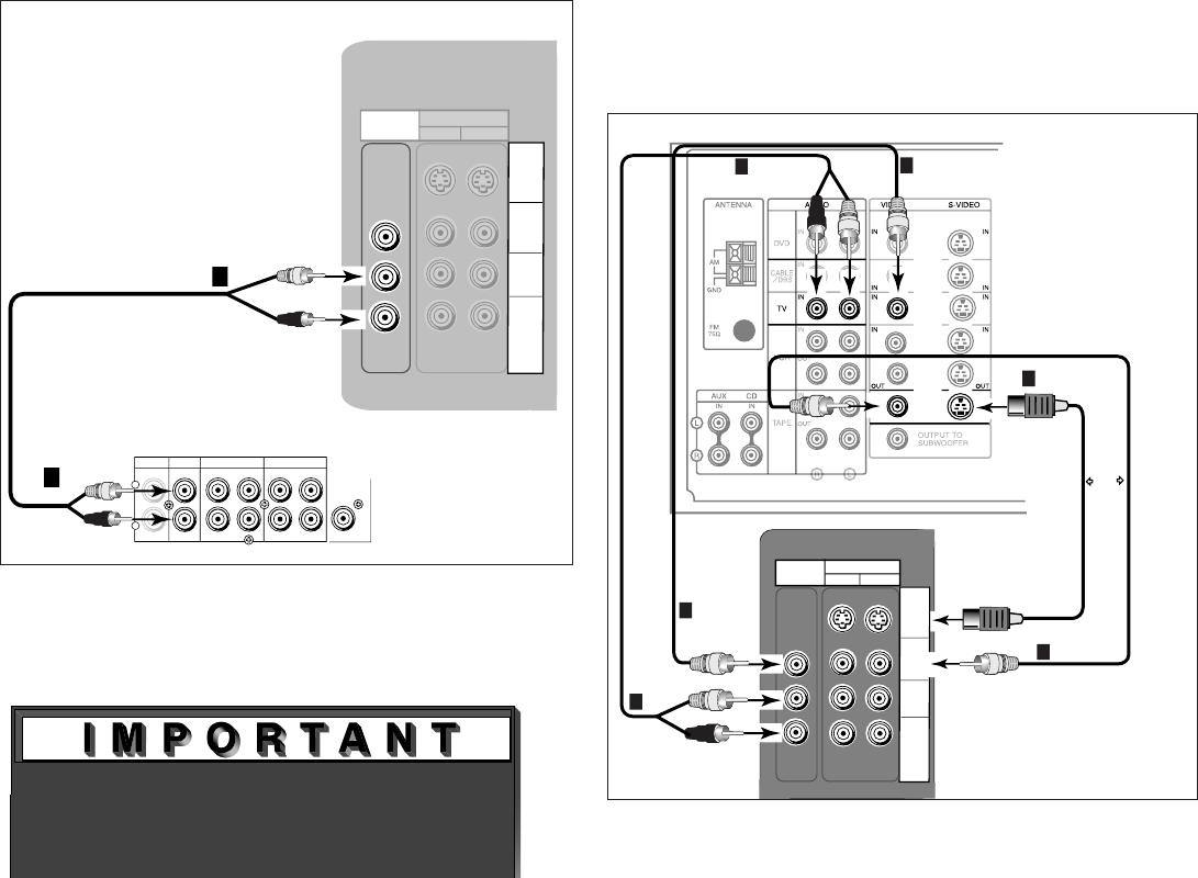
Connecting a Stereo Audio System
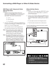
Conecting an Audio Receiver
Stereo Audio System
(Recommended for shelf units or A/V receivers without
digital audio inputs)
(Figure 7)
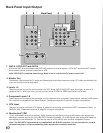
1. Connect the audio cables from AUDIO MONITOR
OUTPUT on the TV back panel to TV IN or AUX IN
terminals on the back of the audio system.
• The red cable connects to the R (right) channel
• The white cable connects to the L (left) channel
2. Use the AUDIO/VIDEO SETTINGS menu (page 50)
to turn off the TV’s speakers.
3. Set the input of the audio system to the TV or AUX
position to hear the TV audio through your stereo
system.
Figure 7. Connecting the Stereo Audio System.
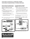
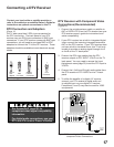
Figure 8. Connecting the A/V Receiver.
Note: Please see your A/V receiver Owner’s
Guide for more detailed connections.
These types of audio connections do
NOT support multi-channel digital audio.
Please refer to your other devices
Owner’s Guide to verify.
A/V Receiver
(Figure 8)
1. Connect either a video cable or an S-Video cable
(but not both) from VIDEO MONITOR OUT on the
back of the A/V receiver to VIDEO INPUT-1 or
INPUT-2 on the TV back panel.
Note: If the A/V receiver outputs an onscreen
menu, this connection allows you to view the
receiver’s menu on the television.
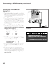
2. Connect a video cable from VIDEO MONITOR
OUTPUT on the TV back panel to VIDEO TV IN on
the back of the A/V receiver.
3. Connect a set of audio cables from AUDIO
MONITOR OUTPUT on the TV back panel to
AUDIO TV IN on the back of the A/V receiver.
• The red cable connects to the R (right) channel
• The white cable connects to the L (left) channel