


PAGE 16 —V304 VIBRATORY ROLLER — OPERATION AND PARTS MANUAL — REV. #8 (11/13/09)
V304 — ROLLER COMPONENTS
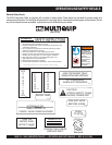
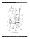
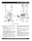
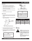
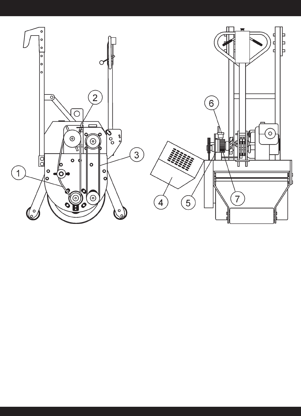
Figure 5 shows the location of additional components for the
V304 compaction roller. The function of each component or
control is described below:
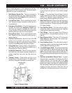
1. Vibration Drive V-Belt – This belt is require to make
the roller vibrate. Check this V-belt as outlined in the
maintenance section of this manual.
2. Free Wheel Engagement Lever – Under normal
conditions this lever should be place in the
forward
position (engaged). In the event the roller becomes
disable and must be moved (will not start), place the
lever in the side position (disengaged).
This will allow the roller drum to rotate (free wheel).
IMPORTANT!, this lever is only to be used in cases
where the roller has be disabled. In normal operating
conditions this lever should be left in the engaged
position (forward)
3. Travel Drive V-Belt – This belt is require to make the
roller travel in a forward or reverse direction. Check this
V-belt as outlined in the maintenance section of this
manual.
4. Compartment Hood – Remove this hood to gain
access to the V-belts, hydrostatic pump, coupling
components, free wheel engagement lever etc.
5. Hydrostatic Pump – Provides hydraulic pressure to
the drive system.
6. Hydrostatic Fluid Reservoir – Fill this reservoir with
hydrostatic transmission fluid. Fill with Mobil 300, GM
Dextron B or Ford MCZ-41A type transmission fluid.
7. Cogged- Drive Belt – This belt is used with the
hydraulic pump. Check this cogged drive belt as outlined
in the maintenance section of this manual.
Figure 5. Roller Components 2