PAGE 28 —V304 VIBRATORY ROLLER — OPERATION AND PARTS MANUAL — REV. #8 (11/13/09)
Adjusting or Changing Vibratory V-Belt
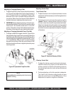
1. To adjust the vibratory V-belt, loosen the pulley tensioner
nut (Figure 33) and adjust the V-belt for approximately 2
to 2-1/2 inches (5 to 6 cm.) of deflection. Check V-belt
deflection when V-belt is pressed midway between the
two pulleys. When the correct amount V-belt deflection
has been achieved, retighten pulley tensioner nut.
2. IMPORTANT! always adjust the vibratory V-belt to the rec-
ommended belt tension. A tight V-belt will cause the roller to
vibrate even it the vibration control lever is in the OFF
position. Remember a loose V-belt will decrease the vibra-
tory action or there may not be any vibratory action at all.
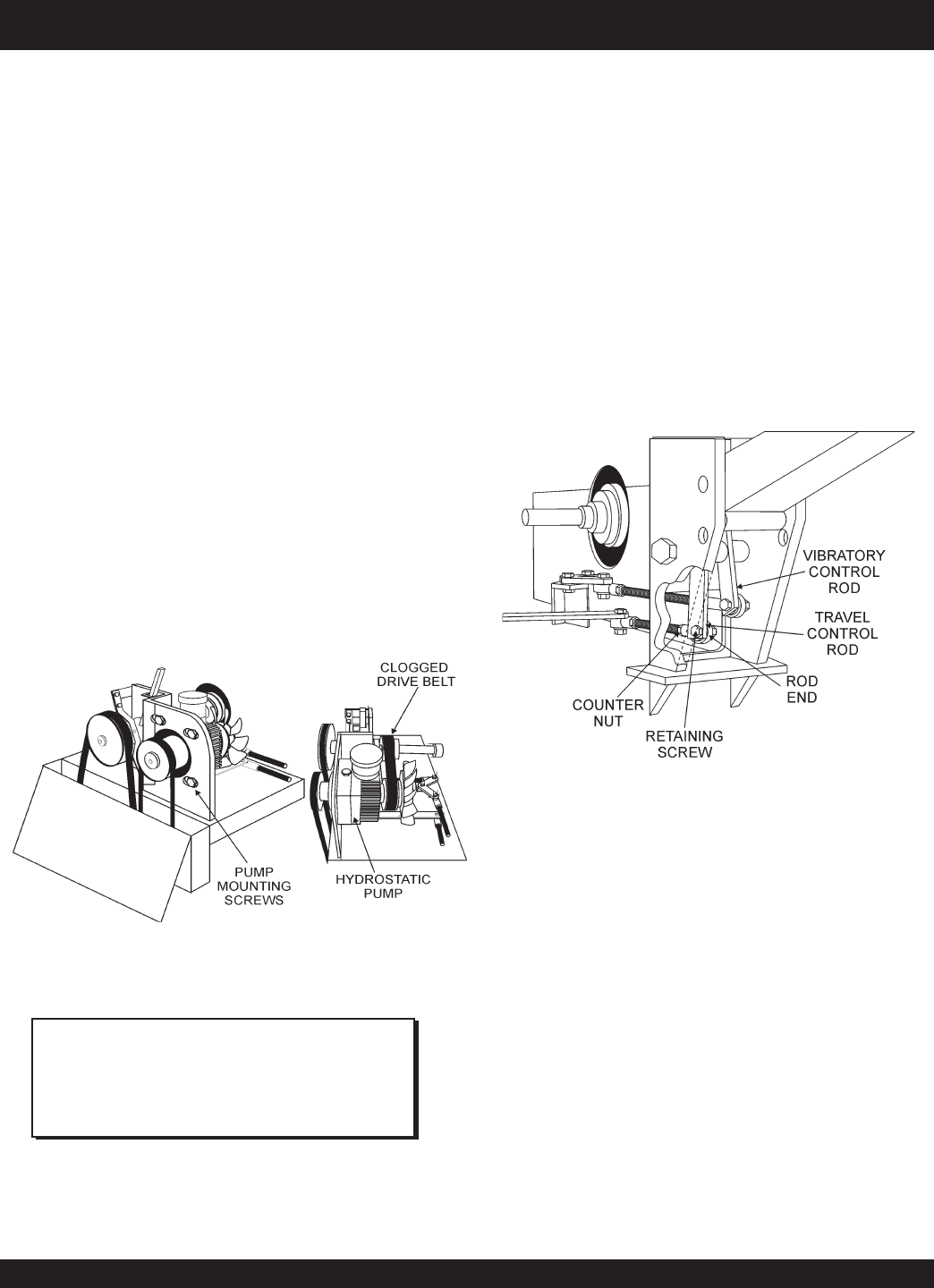
Adjusting or Changing Hydrostatic Pump Drive Belt
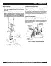
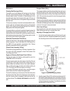
1. To change or adjust the clogged drive belt (Figure 34) for
the hydrostatic pump, loosen the four mounting bolts on the
hydrostatic pump. Move the pump unit towards the rear of the
roller and adjust the clogged belt for approximately 1/2 inch
(1.27 cm) deflection when the belt is pressed midway
between the two pulleys. When the correct amount of belt
deflection has been achieved, retighten hydrostatic pump
mounting screws.
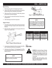
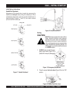
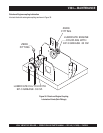
Figure 35. Travel and Vibratory V-Belts
Vibratory Control Rod
1. To adjust the vibratory control rod (controls vibration),
loosen the counter nut (Figure 3) on the rod end of the
vibratory control rod. Remove the retaining screw on
the rod end and rotate the rod to achieve the desired
rod length.
2. Continue adjusting, until clutch operation is adequate.
The V-belt for the vibratory action should not move
when the control lever is in the OFF position. Once
adjustment is complete, retighten all hardware.
Adjusting Control Rods
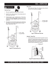
Travel Control Rod
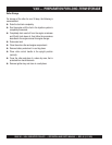
1. To adjust the travel control rod (controls forward, reverse
and neutral) it will be necessary to start the engine and run
it a
low
speed.
2. On the travel control rod, loosen the counter nut on the
rod end
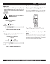
. Remove retaining screw as shown in Figure
35, then rotate the rod end to acquire desired length.
Adjust travel rod so that its static position (no force applied
on drive control) falls into the neutral position. The roller
should not move once adjustment is complete. Retighten
all hardware.
NOTE
Use
caution
when adjusting control rods, since
engine is running.
V304 — MAINTENANCE
Figure 34. Hydrostatic Pump Drive Belt


