12
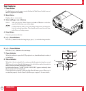
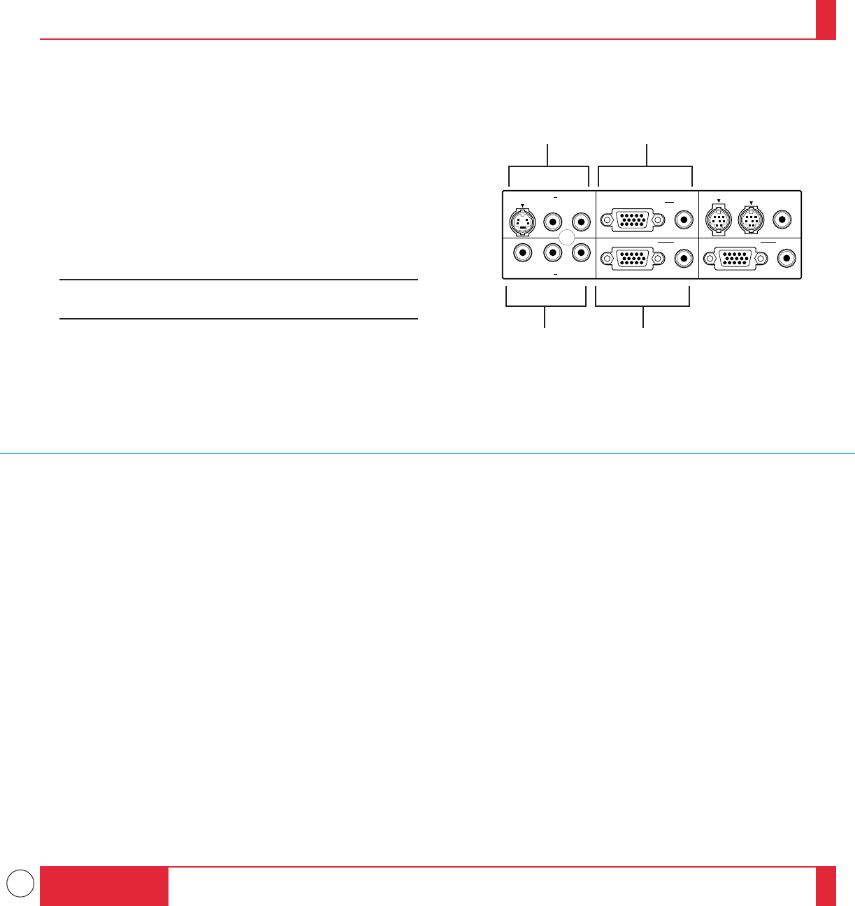
Terminal Panel Features
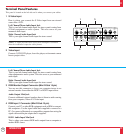
This panel is located on the left side and is where you connect your cables.
INTRODUCTION
21
22
PC CONTROLMOUSE OUTPUT
REMOTE
CONTROL
INPUT
AUDIORGB INPUT 2
AUDIORGB INPUT 1
AUDIORGB MONITOR OUTPUT
RL/MONO
INPUT AUDIOS–VIDEO
RL/MONO
INPUT AUDIOVIDEO
13
24
1 S-Video Input
Here is where you connect the S-Video input from an external
source like a VCR.
Left Channel/Mono Audio Input Jack
This is your left channel audio input for stereo sound coming from
S-Video equipment or audio system. This also serves as your
monaural audio input.
Right Channel Audio Input Jack
This is your right channel audio input for stereo sound.
NOTE: S-Video provides more vivid color and higher resolution
than the traditional composite video format.
2 Video Input
Connect a VCR, DVD player, laser disc player, or document camera
here to project video.
Left Channel/Mono Audio Input Jack
This is your left channel audio input for stereo sound coming from
video equipment or audio system. This also serves as your monaural
audio input.
Right Channel Audio Input Jack
This is your right channel audio input for stereo sound.
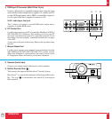
3 RGB Monitor Output Connector (Mini D-Sub 15 pin)
You can use this connector to loop your computer image to an
external monitor from either the RGB 1 or RGB 2 input source.
Audio Output Mini Jack
Connect additional external speakers here to listen to audio coming
from your computer, Video or S-Video input.
4 RGB Input 1 Connector (Mini D-Sub 15 pin)
Connect your PC or other RGB equipment such as IBM or compat-
ible computers. Use the signal cable that's supplied to connect to a
PC. Or connect a Macintosh or compatible computer here using the
signal cable and the pin adapter that is supplied.
RGB 1 Audio Input Mini Jack
This is where you connect RGB audio output from a computer or
another RGB source.


