


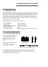
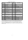


To set a channel to a particular range, read the switch positions as UP or DN (down)
from left to right in the row beside the range you desire.
For example, the ±5V range is: UP>DN>DN>UP>DN.
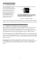
3.6 Installing the CIO-DAC## in the Computer
Turn the power off.
Remove the cover of your computer. Please be careful not to dislodge any of the
cables installed on the boards in your computer as you slide the cover off.
Locate an empty expansion slot in your computer.
Push the board firmly down into the expansion bus connector. If it is not seated
fully it can fail to work and could short circuit the PC bus power onto a PC bus
signal. This could damage the motherboard in your PC as well as the CIO-DAC##.
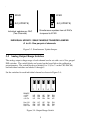
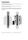
3.7 Cabling to the CIO-DAC##
The CIO-DAC## connector is accessible through the PC/AT expansion bracket.
The connector is a standard 37-pin male connector. A mating female connector,
such as the C37FF-2, is available from OMEGA.
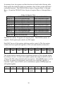
Several cabling and screw termination options are available from OMEGA.
Full featured 4 x 16 in. screw terminal board with
prototyping and interface circuitry
CIO-TERMINAL
Simple, 40-position 4”X4” screw terminal boardCIO-MINI37
5-foot shielded round cable with molded ends
housing 37-pin connectors. Also available in 10-ft.
length.
C37FFS-5
2-foot (and longer) ribbon cable with 37 pin D
connectors
C37FF-2
D connector, D shell and termination pins to
construct your own cable
DFCON-37
3.8 Testing the Installation
You can test the installation of the CIO-DAC## using InstaCal. Select the Test
option to vary the output voltages and monitor them with a Volt Meter.
6