


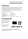
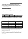

3.3 Wait State Jumper
The CIO-DAC## boards have a wait state jumper which can enable an on-board
wait state generator. A wait
state is an extra delay injected
into the processor's clock via
the bus. This delay slows
down the processor when the
processor addresses the
CIO-DAC## board so that
signals from slow devices
(chips) will be valid.
Figure 3.2. Wait State Jumper
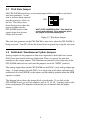
The wait state generator on the CIO-DAC## is only active when the CIO-DAC## is
being accessed. Your PC will not be slowed down in general by using the wait state.
3.4 Individual / Simultaneous Update Jumpers
Analog outputs can be jumpered so that new output data is held until one or more
DACs have been loaded with new digital data. Then, as a group, the new data
transfers to the voltage outputs. The simultaneous transfers occurs when any of the
CIO-DAC## addresses are read (and the jumpers are in the “XFER” position).
The analog output chips on the CIO-DAC## are dual DACs (two analog outputs per
chip). A single jumper sets both DACs on a single chip to be either simultaneously
transferred on a read (XFER) or the ouputs are individually updated when the MSB
register is written.
The diagram below shows the jumper block in each mode. If you look on the
CIO-DAC## board, you will see numbers such as 12, 34, 56... (reading right to left)
below each jumper. The numbers indicate the pair of channels that the jumper
selects.
4
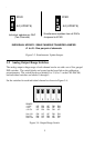
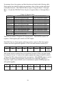
OFFON
WAIT STATE JUMPER BLOCK - This block has
no wait state selected. For a wait state, place
the jumper on the two leftmost pins.