


4 REGISTER ARCHITECTURE
The CIO-DAC## is a simple board to understand. All control and data is
read/written with simple I/O read and write commands. No interrupt or DMA
control software is required. Thus, the board's functions are easy to control directly
from BASIC, C or PASCAL.
4.1 Control & Data Registers
The CIO-DAC16 has 32 analog output registers, the CIO-DAC08 has 16. There are
two registers for each channel; one for the lower 8 bits and one for the upper 4 bits.
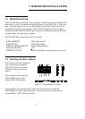
The first address, or BASE ADDRESS, is determined by the setting of a bank of
switches on the board.
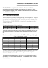
The register descriptions all follow the format:
D12D11D10D9D8D7D6D5
01234567
Where the numbers along the top row are the bit positions within the 8 bit byte and
the numbers and symbols in the bottom row are the functions associated with that
bit.
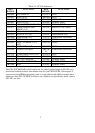
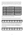
To write to or read from a register in decimal or HEX, the following weights apply:
Table 4-1. Register Bit Weights
801287
40646
20325
10164
883
442
221
110
HEX VALUEDECIMAL VALUEBIT POSITION
To write a control word or data to a register, the individual bits must be set to 0 or 1
then combined to form a byte. Data read from registers must be analyzed to
determine which bits are on or off.
The method of programming to set or read bits from bytes is beyond the scope of
this manual. It is covered in most Introduction To Programming books, available
from a bookstore.
9