


3 HARDWARE INSTALLATION
3.1 Initial Board Setup
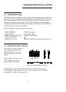
The CIO-DAC## has one bank of gain switches for each analog output channel, one
base address switch, a simultaneous update jumper for each DAC pair, a “power-up
state” selection jumper and one wait state jumper block which must be set before
installing the board in your computer. The InstaCal calibration and test program
included with the CIO-DAC## will show how these switches are to be set. Run the
program before you open your computer.
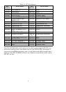
The CIO-DAC## is setup at the factory as follows:
Standard (undefined output values at power up)POWER UP STATE
+
5VANALOG OUTPUT
Single Channel UpdateSIMULTANEOUS UPDATE
Off Position, RightWAIT STATE
300h (768 decimal)BASE ADDRESS
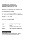
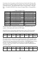
3.2 Selecting the Base Address
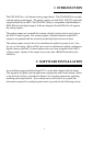
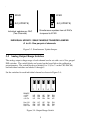
Unless there is already a board in
your system that uses address
300h (768 decimal), leave the
switches as they are set at the
factory.
In the example shown here, the
CIO-DAC## is set for base
address 300h (768 decimal).
Figure 3-1. Base Address Switches
Certain address are used by the PC, others are free and can be used by the
CIO-DAC## and other expansion boards. We recommend you try the factory
default BASE = 300h (768 decimal) first.
2