


.
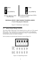
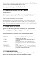
Figure 3-3. Simultaneous Update Jumper
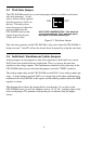
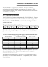
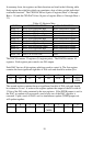
3.5 Analog Output Range Switches
The analog output voltage range of each channel can be set with a set of five ganged
DIP switches. The switch blocks are located on the board below the calibration
potentiometers. The switch blocks are labeled 0 to 15 (0 to 7 on the CIO-DAC08)
and individual switches are labeled 1 through 5.
Set the switches for each individual channel as shown in Figure 3-4..
Figure 3-4. Output Range Switch
5
Simultaneous updates from all DACs
Jumpered to XFER
Individual updates per DAC
(Two Channels)
INDIVIDUAL UPDATE / SIMULTANEOUS TRANSFER JUMPER
J1 to J8 - One per pair of channels.
XFER
# # (UPDATE)
XFER
# # (UPDATE)
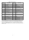
RANGE
+/-10V
+/-5V
+/-2.5V
0 to 10V
0 to 5V
0 to 2.5V
UP
UP
UP
DN
DN
DN
DN
DN
DN
UP
UP
UP
UP
DN
DN
UP
DN
DN
DN
UP
DN
DN
UP
DN
DN
DN
UP
DN
DN
UP
12345