


– 15 –
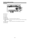
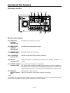
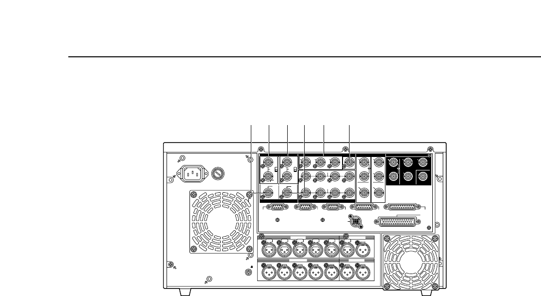
Analog input/output section
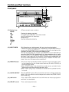
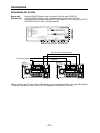
(13) HD REF IN Input of tri-level sync signals as the HD reference signals. A loop-through/75 ≠
connectors termination switch is provided.
(BNCt2)
(14) SD REF IN Input of black burst°
1
signals as the SD reference signals. A loop-through/75 ≠
connectors termination switch is provided.
(BNCt2)
(15) HD REF OUT Output of HD SYNC (tri-level SYNC).
terminal (BNCt1)
(16) SD REF OUT Output of black burst°
2
.
terminal (BNCt1)
(17) VIDEO OUT1, 2, 3 Composite video signal output.
connectors For OUT3, superimpose output is also possible.
(BNCt3)
(18) WFM (waveform) Signals output to the waveform monitor.
connector
°
1
When the normal black burst signal (59.94 Hz) is input as the SD REF signal with the 1080/24p system,
asynchronization and a picture error will result.
°
2
This signal is not output with the 1080/24p system.
~
AC IN
SIGNAL
GND
OUTPUT
CH CH CH CH
INPUT
CH CH CH CH
HD
HD
REMOTE
IN
ON
OFF
123
(
SUPER
)
(
SUPER
)
IN
IN
OUT
HD SDISD SDIWFMVIDEO OUTREF IN
REF OUT DIGITAL AUDIO
1
OUT1
OUT2
OUT
2
OUT
3
MONITOR
MONITOR
(
SUPER
)
SPARE
ACTIVE
THROUGH
REMOTE
OUT
REMOTE
IN/OUT
CONTROL
PANEL
V/A
CONTROL
RS-232C
PARALLEL
IN/OUT
(
50P
)
SD
SD
SD
ON
OFF
FUSE
125V 5A
ACTIVE
THROUGH
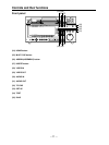
(15)(13)(14)(16)(17) (18)
CH 1 CH 2 CH 3 CH 4
CH 1 CH 2 CH 3 CH 4
CUE
CUE
LR
OUT
IN
AUDIO OUT
AUDIO IN
MONITOR
TIME CODE
PUSH
PUSH PUSH PUSH PUSH PUSH
75Ω 75Ω
3
4
π
1
2
π
7
8
π
5
6
π
7
8
π
5
6
π
3
4
π
1
2
π
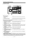
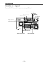
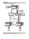
Controls and their functions
Connector section