


– 8 –
Parts and their functions
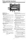
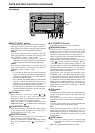
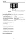
Front panel
Digital Video Cassette Recorder AJ-
SUPER
ON
OFF
TCG
REGEN
PRESET
EXT
INT
COUNTER
PF PF
1
PF
2
PF
3DIAG
MENU
PUSH
SHTL/SLOW
TC
PRESET
METER
FULL/FINE
MONITOR SEL
RESET
REC PB
UNITY
INPUT SELECT
VIDEO AUDIO
CH 1 CH 2 CH 3 CH 4
HEADPHONES
SEARCH
EJECT
POWER
REC INHIBITCONTROL
ON
ON
OFF
OFF
LOCAL
REMOTE
RECPLAY
FFREW STOP
POWER switch
Cassette insertion slot
EJECT button
When this button is pressed, the tape is unloaded and
the cassette is ejected automatically a few seconds
later.
When CTL display has been selected for the counter
display, the display is reset.
EJECT button operation can be enabled or disabled
with setup menu No. 115 (EJECT SW INH).
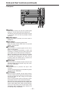
CONTROL switch
This is selected to control the unit from an external
source using the REMOTE connector.
REMOTE: Set to this position to control the unit using
the 9-pin REMOTE connector and IEEE
1394 AV/C commands.
LOCAL : Set to this position to control the unit using
the controls on the unit's operation panel.
REC INHIBIT switch
This switch is used to enable or disable recording on
the cassette tape.
ON:
Recording on the cassette tape is disabled
(inhibited).
In this state, the REC INH lamp lights on the display
panel.
OFF:
Recording on the cassette tape is enabled so long
as the accidental erasure prevention mechanism on
the cassette tape is set to enable recording.
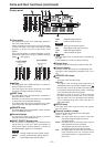
METER (FULL/FINE) selector button
This button is used to select the scale display for the
audio level meter.
FULL mode : The standard scale (– ∞ to 0 dB) is
selected.
FINE mode : The scale in 0.5 dB increments is
selected. The position indicates
the standard level of –20 dB (–18 dB).
(See page 11)
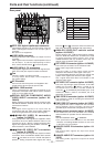
MONITOR SEL button
This button is used to select the audio signals which
are to be output to the AUDIO MON L and R
connectors.
Each time the button is pressed, the audio signals to
be output to the AUDIO MON L or R connector are
changed in the following sequence.
Which signal is currently selected is displayed by the
lighting of the L or R lamp on the level meter display.
Headphone jack and volume control
When stereo headphones are connected to the
headphone jack, the sound can be monitored using
the headphones during recording or playback.
Audio level control knobs
These knobs are used to adjust the recording and
playback level of the PCM audio signals (CH1, CH2,
CH3 and CH4).
Whether the recording level or playback level is to be
adjusted is selected using the audio level control
selector switch .
Note:
The level of the IEEE 1394 digital input/output audio
signals cannot be adjusted.
Audio level control selector switch
UNITY: At this position, the audio signals are recorded
or played back at a fixed level regardless of
the position of the audio level control knobs
.
REC : At this position, the audio signals are
recorded at the level which has been adjusted
by the audio level control knobs .
PB : At this position, the audio signals are played
back at the level which has been adjusted by
the audio level control knobs .
Note:
It is not possible to set this switch so that both the
recording level and playback level can be adjusted.
When REC is selected, UNITY (fixed level) is set for
the playback level; when PB is selected, UNITY is set
for the recording level.
L : [CH1] [CH3] [CH1] [CH2] [CH3] [CH4]
R : [CH2] [CH4] [CH1] [CH2] [CH3] [CH4]
[CH1+CH2] [CH3+CH4]
[CH1+CH2] [CH3+CH4]
→→→→→
→→