


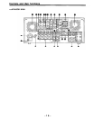
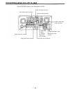
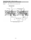
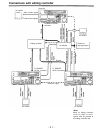
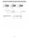
<Connector area>
AC IN connector
This is for connecting the unit to the power outlet using the power cord provided.
SIGNAL GND terminal
This terminal is connected to the signal ground terminal of the connected unit in order to
reduce noise. It is not connected to ground for safety purposes.
Fuse holder
This contains a fuse.
Fan motor
This is for cooling the unit.
The
lamp lights when trouble has caused the fan motor to stop. If the unit is still
operated in the warning status, the temperature inside the deck will rise, and when it
exceeds the safety temperature, all the unit’s operations will be shut down.
TIME CODE IN connector
This is the connector for recording the external time code on the tape.
TIME CODE OUT connector
The playback time code is output from this connector during playback.
During recording, the time code generated by the internal time code generator is output.
CUE IN connector
The analog signal to be recorded on the CUE track is supplied to this connector. The
audio signals from a microphone can also be recorded by selecting the -60dB input mode
on the setup menu No. 705 (CUE IN LV).
CUE OUT connector
The analog signal recorded on the CUE track is output from this connector.
MONITOR OUT connector
During playback, the playback signals from the CUE track or PCM audio signal CH1/CH2/
CH3/CH4 are output from this connector.
ANALOG AUDIO IN connectors
These are the analog audio input connectors.
ANALOG AUDIO OUT connectors
The analog audio signals are output from these connectors.
SDTI IN/OUT connector (option)
ANALOG COMPONENT VIDEO IN connector
The analog component video signal is supplied to this connector.
ANALOG COMPOSITE VIDEO IN connectors and 75 termination switch
The analog composite video signal is supplied to these two connectors which are
connected in a loop-through configuration. When the termination is required, set the
switch to ON.
REF VIDEO IN connectors and 75 termination switch
These are the input connectors for the reference video signals. Supply signals with color
burst. When the termination is required, set the switch to ON.
-17-