


RQT8314
8
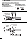
STEP 1 Connection
This section includes diagrams of four common methods of connections (A-D, pages 8-9). Please connect using the one that best suits
you.
• Visit Panasonic’s homepage for more information about connection methods. (This is in English only.)
http://www.panasonic.com/consumer_electronics/dvd_recorder/dvd_connection.asp
• Before doing any connection, turn off all equipment and read the appropriate operating instructions.
• Peripheral equipment and optional cables are sold separately unless otherwise indicated.
n The unit’s RF OUT terminal
The picture and sound signal from this unit does not go
through the RF OUT terminal to the television.
Make sure you connect one of the following terminals on this
unit to the television: the AUDIO/VIDEO OUT terminal, the S
VIDEO OUT terminal or the COMPONENT VIDEO OUT
terminal.
• Refer to page 11 if the antenna connector doesn’t match.
n When the unit is not to be used for a long time
To save power, unplug it from the household AC outlet. This unit
consumes a small amount of power, even when it is turned off
(approx. 2.0 W
).
n Connect the unit directly to the television
Video signals fed through video cassette recorders will be
affected by copyright protection systems and the picture will
not be shown correctly on the television.
The connection will allow the video cassette recorder to be used for playback and recording when this unit is turned off.
Te lev i s io n
VCR
Television
This unit VCR
This unit
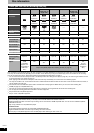
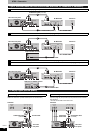
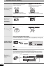
A Connection with a television
B
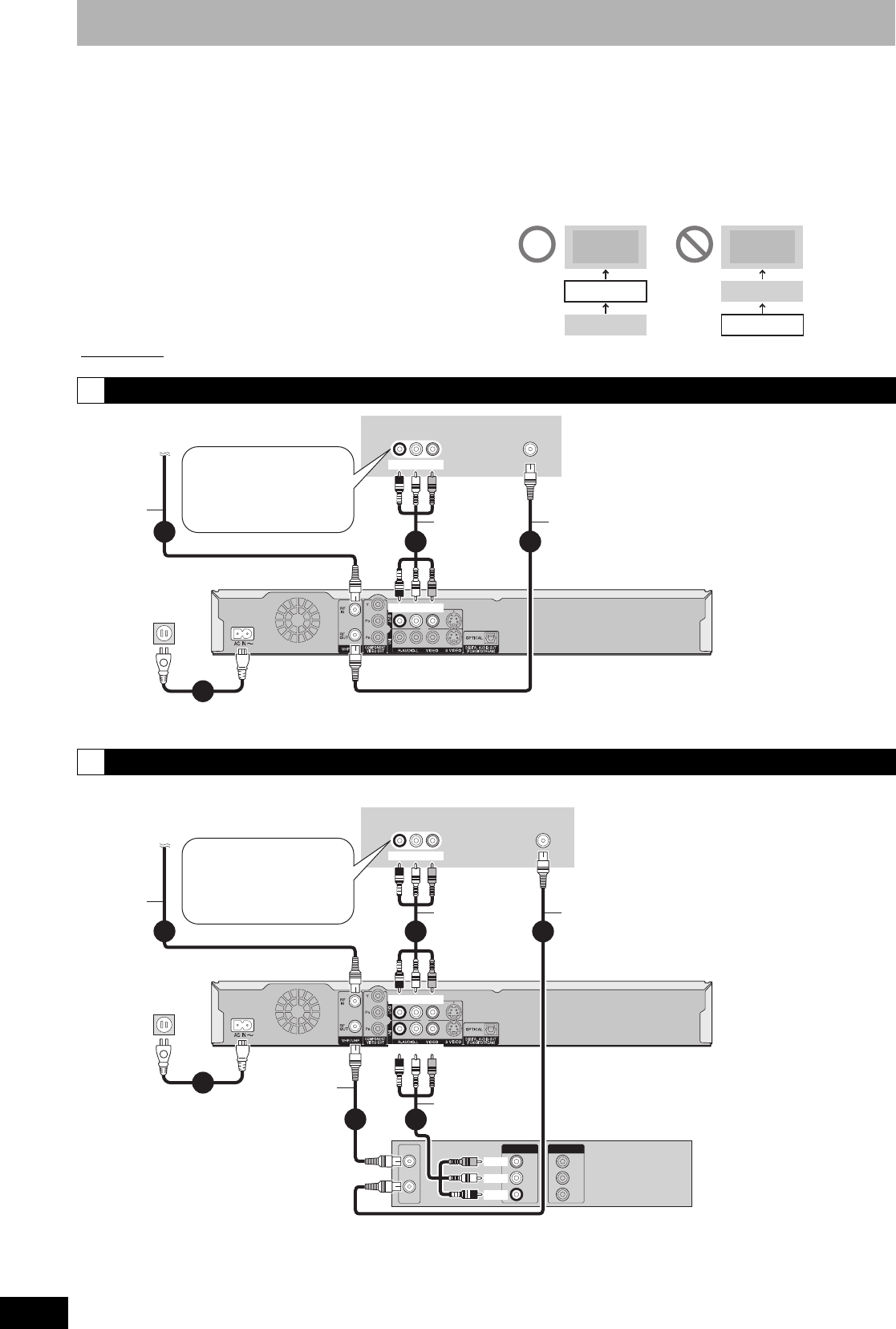
Connection with a television and video cassette recorder
VHF/UHF
RF IN
AUDIO IN
R L
VIDEO
IN
3
1
4
2
AC power supply cord (Included)
Connect only after all other connections are complete.
To household
AC outlet
(AC 120 V, 60 Hz)
Television
75 Ω coaxial cable
(Included)
Cable from wall or
antenna signal
75 Ω
coaxial
cable
This unit’s rear panel
Red White Yellow
• If your television does not
have AUDIO/VIDEO
terminals (Ô page 10 a).
• If you enjoy higher picture
quality (Ô page 10).
Red White Yellow
To OUT
To RF IN
To RF OUT
Audio/video
cable
(Included)
VHF/UHF
RF IN
VHF/UHF
RF IN
VHF/UHF
RF OUT
AUDIO
R
AUDIO
L
VIDEO
OUT
OUT
AUDIO
R
AUDIO
L
VIDEO
IN
IN
AUDIO IN
R L
VIDEO
IN
3
2
5
4
6
1
AC power supply cord
(Included)
Connect only after all
other connections are
complete.
To household
AC outlet
(AC 120 V, 60 Hz)
Television
Audio/video
cable
(Included)
75 Ω coaxial cable
Cable from wall or
antenna signal
75 Ω
coaxial
cable
This unit’s rear panel
Red White Yellow
• If your television does not
have AUDIO/VIDEO
terminals (Ô page 10 b).
• If you enjoy higher picture
quality (Ô page 10).
Red White Yellow
75 Ω coaxial
cable
(Included)
Audio/video
cable
Video cassette recorder
Yellow
White
Red
To OUT
To RF IN
To RF OUT
To IN1
Red White Yellow