


Getting started
RQT5741
10
480P COMPONENT VIDEO OUT
P
B
YP
R
P
B
YP
R
(PCM/BITSTSTREAM)
RL
OPTICAL COAXIAL
CENTER SURROUND R/
FRONT R
L/
FRONT L
R
L
SUB-
WOOFER
S VIDEO OUT
AC IN
COMPONENT VIDEO OUT
VIDEO OUT
DIGITAL AUDIO OUT
AUDIO OUT
5.1 ch 2 ch
AUDIO OUT
2 ch
PRPBY
PRPBY
AUDIO
IN
L
R
VIDEO
IN
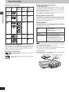
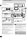
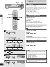
Connection to a television
Although the audio on most DVDs is designed to be played through six speakers and this unit’s factory settings assume this setup, the following
describes the most basic connections that allow you to enjoy sound through your television’s speakers. To get the full benefit from the powerful
5.1-channel audio found on DVDs, you should connect a receiver and six speakers. Descriptions of this kind of connection start on page 35.
Before connection
³Disconnect the AC power supply cord.
³Refer to the television’s operating instructions.
[A] 480P COMPONENT VIDEO OUT terminal
These are progressive video terminals. To enjoy progressive video
(480P), connect this unit to the component (480P) video input con-
nections on a television that is compatible with the unit’s copy guard
system.
³All televisions manufactured by Panasonic and that have 480P in-
put connectors are compatible. Consult the manufacturer if you
have another brand of television.
³The picture will not be shown if you connect to non-progressive
input terminals.
[B] COMPONENT VIDEO OUT terminal
Connection using these terminals outputs the color difference sig-
nals (P
B/PR) and luminance signal (Y) separately in order to achieve
high fidelity in reproducing colors.
³These are 480I interlace output terminals.
[C] S VIDEO OUT terminal
The S-video terminal achieves a more vivid picture than the VIDEO
OUT terminal by separating the chrominance (C) and luminance (Y)
signals. (Actual results depend on the television.)
Note
³Do not connect to component (480P) video input connectors if
your television is incompatible with this unit’s copy guard system
as the video will not be displayed correctly.
³The description of the component video input terminals depends
on the television or monitor (e.g. Y/P
B/PR, Y/B-Y/R-Y, Y/CB/CR).
Connect to terminals of the same color.
³After making connection [A] or [B], change the black level for a
better picture (➡ page 31, Video—Black Level Control).
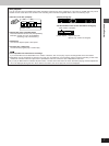
Conserving power
This unit consumes a small amount of power, even when it is turned
off (approx. 2 W ). To save power when the unit is not to be used for
a long time, unplug it from the household AC outlet.
Connect Your Unit Directly To Your Tele-
vision.
Do not connect the unit through your video cassette recorder
when setting up your home entertainment system, because
the picture may not be played correctly due to the copy guard.
To
household
AC outlet
(AC 120 V,
60 Hz)
Television
AC power
supply cord
(included)
Back of the unit
[C] S VIDEO OUT terminal
[B] COMPONENT VIDEO OUT terminal
S video cable (not included)
TV’s
S video
input
terminal
Video cable
(not included)
TV’s component
(480I) video input
terminals
P
R terminal
P
B terminal
Y terminal
Video cable/Audio cable (included)
Yellow (VIDEO)
White (L)
Red (R)
Video cable
(included)
Audio cable
(included)
[A] 480P COMPONENT VIDEO OUT terminal
Video cable
(not included)
TV’s component
(480P) video input
terminals
P
R terminal
P
B terminal
Y terminal
BNC–RCA
adaptor plug
(included)
Side view
of the
terminal
Turn clockwise.
Attach the adapter so
the terminal’s protrusion
fits into its hole.
BNC–RCA
adaptor plug
(included)
To the AUDIO
IN terminals
on another
piece of
equipment