


14
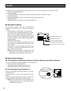
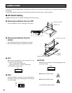
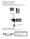
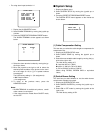
■ Connection with a Time Lapse VCR
Connect the time lapse VCR as shown in the example below.
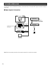
Make sure the polarity of the buzzer matches the terminal.
Connect the positive (+) terminal of the buzzer to the Alarm Output Terminal.
The Alarm Output Terminal is an Open Collector terminal with a capacity of 16 V DC, 100 mA or less.
(1) Connect the buzzer as shown below if its rating lies within the capacity of the Alarm Output Terminal.
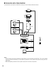
(2) Use an external relay unit as shown below if the buzzer rating exceeds the capacity of the Alarm Output Terminal.
GND
ALARM IN
ALARM OUT
1
2
G34
Relay
+12 V
NC
NO
Alarm Indicator etc.
Time Lapse VCR
1 ALARM IN
2 ALARM OUT
G ROUND
3 RECOVER IN
4 RESET OUT
NC: Normally Closed Contact
NO: Normally Open Contact
2 4
ALARM
IN
1
COM2
ALARM
RESET IN
3
ALARM
RECOVER OUT
4
ALARM
OUT
5
135
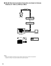
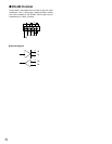
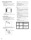
■ Cable-loss Compensation Setting
The maximum allowable cable length of the system is approximately 900 m (3 000 ft).
See the diagram below and setup the cable-loss compensation switch for each unit accordingly. (See page 19)
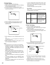
Camera WV-CU161
A m (A ft)
<Example>
0 (0)≤ A < 400 (1 300) → S
400 (1 300) ≤ A < 700 (2 300) → M
700 (2 300) ≤ A < 900 (3 000) → L
Cable compensation
parameter in WV-CU161
Setup menu
Cable length (with RG-59U
BELDEN 9259 or equivalent)
Unit: m (ft)