


8
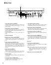
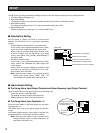
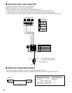
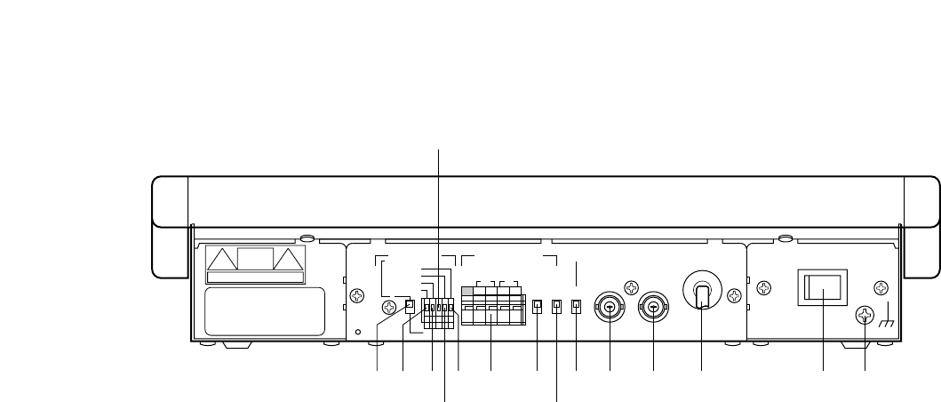
■ Rear View
POWER
OFF
SIGNAL GND
ON
CAMERA
IN
RS485ALARM DATA
TERM
VIDEO
OUT
RESET OUT
ALARM IN
RECOVER IN
ALARM OUT
ALARM IN
LINE
COAX
RS485
4
2
ON
OFF
12G34
RT
ABABG
q
w
o
i !0 !1 !2 !3 !4 !5u
rt
e
y
q Alarm Input Terminal (ALARM IN)
Accepts the alarm signals from external devices such
as alarm sensor when the alarm switch y is in the
upper position.
w Alarm Output Terminal (ALARM OUT)
The alarm output signal is provided at this terminal for
the Time Lapse VCR etc. when the alarm switch y is in
the upper position.
(Open collector output, 16 V DC or less, 100 mA or
less)
e Ground Terminal (G)
r Recover Input Terminal (RECOVER IN)
Accepts the alarm recover signal from the Time Lapse
VCR etc. when the alarm switch y is in the upper posi-
tion.
t Reset Output Terminal (RESET OUT)
When the Alarm Reset Switch is pressed or the Recover
Input Terminal r is input to reset the activated alarm,
and the alarm switch y is in the upper position, the
alarm reset signal for the peripherals is provided at this
terminal.
y Alarm Switch (ALARM IN)
Used to select the alarm mode.
When this switch is in the lower position, the terminals
q, w, r and t above are used for alarm inputs 1 - 4.
u RS-485 Terminal
This terminal is used to exchange control data with the
camera site.
i Termination Switch (TERM ON/OFF)
This switch is used to terminate the RS-485 terminal.
Normally, keep it in the ON position.
o Line Selection Switch (LINE 4/2)
This switch is used to select either Full-duplex (4-lines)
or Half-duplex (2-lines) for the communication lines.
!0 Data Selection Switch (COAX/RS485)
This switch selects either multiplex coaxial data or RS-
485 data from control data with the camera site.
!1 Video Output Connector (VIDEO OUT)
Video signals from the camera are output from this con-
nector.
!2 Camera Input Connector (CAMERA IN)
This connector accepts the multiplexed video and con-
trol data signal from the specified camera such as WV-
CS854, WV-CS654 or WV-CS604 or a specified receiv-
er.
!3 AC Cord
!4 Power Switch (POWER ON/OFF)
This switch is used to turn the power of the System
Controller on and off.
Note: Turning off this switch will not interrupt the power
supply. Disconnect the AC cord or turn off the cir-
cuit breaker when the controller is not used for a
long time.
!5 Signal Ground Terminal (SIGNAL GND)