


18
19
Quick Start
Guide
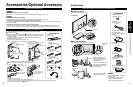
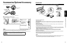
Identifying Controls
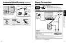
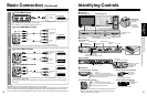
Basic Connection (AV cable connections)
High-Definition
Standard-Definition
Note
Some programs contain a copyright protection signal to prevent recording.
When the copyright protection program is displayed, do not connect the other TV monitor through a VCR. Video signals fed
through VCRs may be affected by copyright protection systems and the picture will be distorted on the other TV monitor.
For more details on the external equipment’s connections, please refer to the operating manuals for the equipment.
CH
S VIDEO
VIDEO
VIDEO IN 2
L-AUDIO-R
VOL
INPUT/OK
MENU
POWER
AV IN
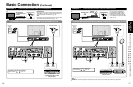
Basic Connection (Continued)
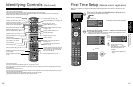
Identifying Controls
Power button
HDMI terminal
(For Tuner Box
or Wireless Unit
connection)
Front of Display Unit
A
To use HDMI terminals
AV IN
HDMI
AV OUT
e.g. Blu-ray Disc player
AV Equipment
Connecting to HDMI terminals will enable you to enjoy high-definition digital images and high-quality sound.
The HDMI connection is required for a 1080p signal.
For “VIERA Link
TM
connections”, please refer to p. 45.
B
To use COMPONENT terminals
L
R
Y
P
B
PR
COMPONENT
VIDEO OUT
AUDIO
OUT
white
red
green
blue
red
white
red
green
blue
red
white
red
green
blue
red
e.g. Blu-ray Disc
player
AV Equipment
Recorders may also be connected to COMPOSITE or S VIDEO terminals. (see below)
C
To use S VIDEO terminals
L
R
white
red
white
red
AUDIO
OUT
S VIDEO
OUT
white
red
or
e.g. DVD Recorder
AV Equipment
e.g. VCR
D
To use COMPOSITE terminals
L
R
COMPOSITE
OUT
yellow
white
red
yellow
white
red
yellow
white
red
or
e.g. DVD Recorder
AV Equipment
e.g. VCR
The S Video input will override the composite video signal when S Video cable is connected. Connect
either S Video or Video cable.
Connecting to S VIDEO terminals will enable you to enjoy greater picture quality than using Composite
terminals.
AV cable connections TV controls/indicators
■
Display Unit
Back of Display Unit
DC terminal
(For Wireless
Unit connection)
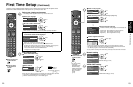
Front of Tuner Box
■
Tuner Box
Back of Tuner Box
HDMI 4 terminal
VIDEO IN 2
terminals
PC terminal
SD card slot
Other terminals
p. 62
DC terminal
(For Wireless Unit connection)
HDMI AV OUT terminal
(For Display Unit
or Wireless Unit
connection)
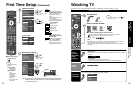
Front of Wireless Unit (Transmitter)
■
Wireless Unit
Front of Wireless Unit (Receiver)
Back of Wireless Unit (Transmitter)
Back of Wireless Unit (Receiver)
AV terminal
(For Tuner Box
connection)
AV terminal
(For Display Unit
connection)
DC terminal
(For Tuner Box connection)
DC terminal
(For Display Unit connection)
Off: Power off
Red: Power on and no communication
Green: Power on and communication state good
Orange: Power on and communication state not good
Red (blinking): Indicates malfunction
Off: Power off
Red: Power on and no communication
Green: Power on and communication state good
Red (blinking): Indicates malfunction
Changes the input mode
Chooses menu and submenu entries.
Displays the
Main menu.
Volume up/down
Selects channels
in sequence
Power button
Remote control sensor
C.A.T.S. sensor. (Contrast
Automatic Tracking System).
Power indicator
(On: red, Standby: orange, Off: no light)
When the red LED is blinking, turn the power of the Tuner Box and
Display Unit off and then on again. If the problem is not resolved,
consult your local Panasonic dealer.
Volume up/down
Selects channels in
sequence
Power indicator
(on: red, off: no light)