


22 Pelco Manual C673M (2/01)
REAR PANEL
WARNING:
The included
power cord is used for 120
VAC, 60 Hz. Never connect
the power cord to any output
or power supply having a dif-
ferent voltage or frequency.
Make sure the power cord is
unplugged before making
any rear panel terminal
connections.
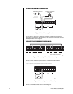
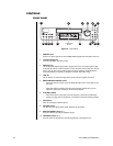
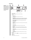
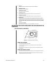
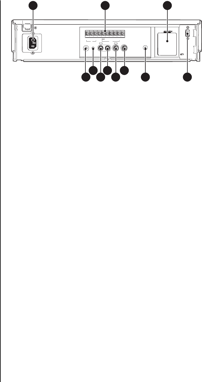
Figure 11. Rear Panel
1. AC power socket
The power cord plugs into this socket. Insert the cord firmly.
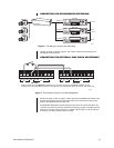
2. Terminals
• Input Terminals
ALM (alarm) IN
Use for alarm recording. Connect the alarm sensor here.
RST (reset) IN
Connect the alarm reset switch here to stop alarm recording when ALARM REC
DURATION in the Recording Set Up menu is set to MAN1. You can also use this
terminal to set the on-screen clock when set to any mode other than MAN1.
REC (recording) IN
Use to start and stop recording or for series recording (refer to the
Series
Recording
section).
• GND (ground)
Connect the ground lead here when a lead connected to other terminals requires
a ground.
• Output Terminals
ALM (alarm) OUT
Use to indicate to an external device that an alarm is being recorded.
MODE OUT
Use to indicate the VCR’s mode of operation. When MODE OUT in the Rear
Terminal menu is set to CLOCK ADJ, the clocks of all connected VCRs can be
adjusted.
CLK (clock) OUT
Use to control an external camera switcher, such as the MX4000 Series Genex
Multiplexer.
CALL OUT
Use to indicate when the tape finishes recording or that there was a problem
during recording.
3. Battery box
The battery is stored here. (
NOTE:
This is a special battery. Consult your dealer to
replace it.
)
4. REMOTE jack
Jack for connecting a remote control unit.
00442
REMOTE
RESET
IN OUT
AUDIO
IN OUT
VIDEO
ALM RST GNDREC MODE CLKCALL
IN OUT
BATTERY OPEN
1 2 3
4
7
10
5 9
86 11
MIC