


8
RS-232C Adjustment Mode
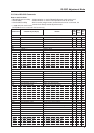
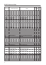
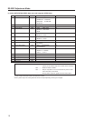
GRA GRADATION: ####### Displays the current GRADATION setting ¶
GRAS01 GRADATION: GAMMA 2.0 Sets GRADATION to ‘GAMMA 2.0’. ‡
GRAS02 GRADATION: GAMMA 1.8 Sets GRADATION to ‘GAMMA 1.8’. ‡
GRAS03 GRADATION: GAMMA 2.2 Sets GRADATION to ‘GAMMA 2.2’. ‡
GRAS04 GRADATION: DRE MID Sets GRADATION to ‘DRE MID’. ‡
GRAS05 GRADATION: DRE HIGH Sets GRADATION to ‘DRE HIGH’. ‡
GRAS06 GRADATION: DRE LOW Sets GRADATION to ‘DRE LOW’. ‡
GRAS07 GRADATION: HIGH CNT. Sets GRADATION to ‘HIGH CONTRAST’. ‡
GSL G SIDE MASK LEVEL: ∗∗∗ Adjusts the GREEN side mask. ‡‡
GSO (GET STATUS OPTIONDATA) Gets OPTION data. ¶¶
GSS (GET STATUS SETUP DATA) Gets SETUP data. ¶¶
GST (GET STATUS) Gets STATUS. ¶¶
GWB (GET WHITE BAL.DATA) Gets integrator WHITE BALANCE data. ¶¶
[H]
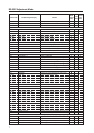
HPS H. POSITION: ∗∗∗ Adjusts the HORIZONTAL POSITION. ‡‡
HSI H. SIZE:∗∗∗ Adjusts the HORIZONTAL SIZE. ‡‡
[I]
IDC ID CLEAR Clears the ID. ‡
DS ID No.: ∗∗ Sets the ID. ‡‡
IN1 INPUT1 Switches the main screen to INPUT1. ‡‡
IN2 INPUT2 Switches the main screen to INPUT2. ‡‡
IN3 INPUT3 Switches the main screen to INPUT3. ‡‡
IN4 INPUT4 Switches the main screen to INPUT4. ‡‡
IN5 INPUT5 Switches the main screen to INPUT5. ‡‡
INP INPUT#
Displays the current input function for the main screen.
¶¶
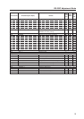
INPS01 INPUT1 Switches the main screen to INPUT1. ‡‡
INPS02 INPUT2 Switches the main screen to INPUT2. ‡‡
INPS03 INPUT3 Switches the main screen to INPUT3. ‡‡
INPS04 INPUT4 Switches the main screen to INPUT4. ‡‡
INPS05 INPUT5 Switches the main screen to INPUT5. ‡‡
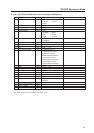
[L]
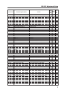
LEN FRONT INDICATOR: OFF Turns OFF the front indicator. ‡
LEY FRONT INDICATOR: ON Turns ON the front indicator. ‡
LNN LOUDNESS: OFF Disables LOUDNESS. ‡‡
LNY LOUDNESS: ON Enables LOUDNESS. ‡‡
[M]
MCD COLOR DECODING: ∗∗∗∗∗∗ Displays the current COLOR DECODING. ¶
MCDS01 COLOR DECODING: RGB Sets COLOR DECODING to RGB (VIDEO). ‡
MCDS02 COLOR DECODING: COMPONENT1 Sets COLOR DECODING to COMPONENT1 (Y CbCr). ‡
MCDS03
COLOR DECODING: COMPONENT2
Sets COLOR DECODING to COMPONENT2 (Y PbPr). ‡
MCN MASK CONTROL: OFF Turns OFF MASK CONTROL. ‡
MCY MASK CONTROL: ON Turns ON MASK CONTROL. ‡
MGF ############# Displays the 2 x 2 ON/OFF status. ¶¶
MGFS00 2 x 2: OFF Turns OFF 2 x 2 (4-screen multi). ‡‡
MGFS01 2 x 2: ON Turns ON 2 x 2 (4-screen multi). ‡‡
MGP #############
Displays the current 2 x 2 seam-consideration/magnification position.
¶
MGPS01 2 x 2 NORMAL UP LEFT Sets 2 x 2 to upper left (no seam consideration). ‡
MGPS02 2 x 2 NORMAL DOWN LEFT Sets 2 x 2 to lower left (no seam consideration). ‡
MGPS03 2 x 2 NORMAL UP RIGHT Sets 2 x 2 to upper right (no seam consideration). ‡
MGPS04 2 x 2 NORMAL DOWN RIGHT Sets 2 x 2 to lower right (no seam consideration). ‡
MGPS05 2 x 2 ADJUSTED UP LEFT Sets 2 x 2 to upper left (seam consideration). ‡
MGPS06 2 x 2 ADJUSTED DOWN LEFT Sets 2 x 2 to lower left (seam consideration). ‡
MGPS07 2 x 2 ADJUSTED UP RIGHT Sets 2 x 2 to upper right (seam consideration). ‡
MGPS08 2 x 2 ADJUSTED DOWN RIGHT Sets 2 x 2 to lower right (seam consideration). ‡
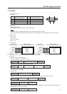
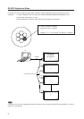
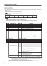
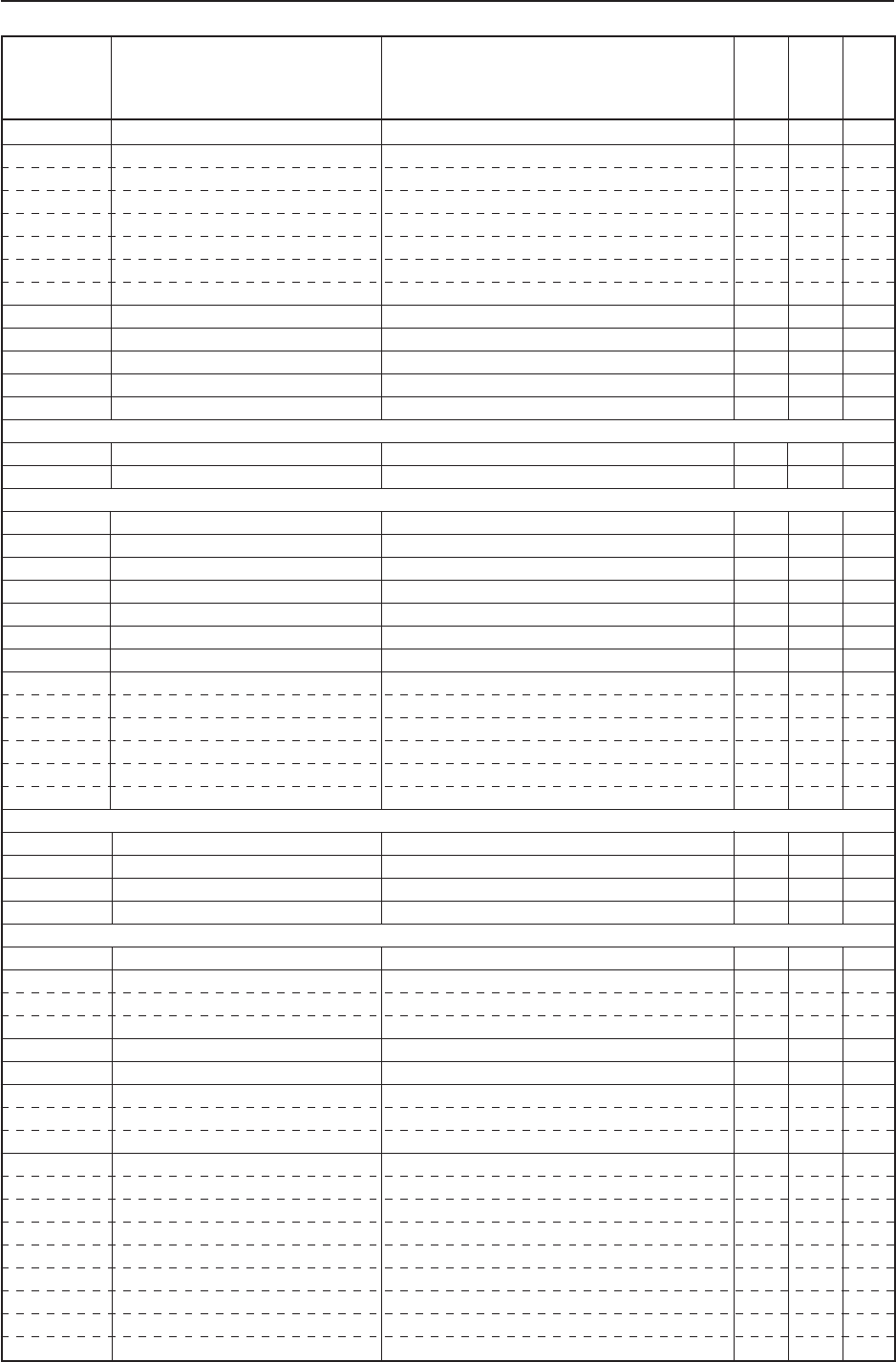
Command name AJY (232C integrator) Display
RS-232C
Adjustment
Validity
Normal
Validity
Numerical
Direct
Validity
Remarks