


7
RS-232C Adjustment Mode
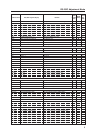
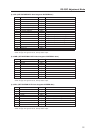
CTR CTI: ### Displays the current CTI setting. ¶
CTRS00 CTI: OFF Sets CTI to OFF. ‡
CTRS01 CTI: ON Sets CTI to ON. ‡
[D]
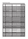
DIN Turns OFF the OSD display. ‡‡
DIY OSD: ON Turns ON the OSD display. ‡‡
DNR DNR: ###### Displays the current DNR setting. ¶
DNRS00 DNR: OFF Sets digital NR to ON. ‡
DNRS01 DNR: LOW Sets digital NR to LOW. ‡
DNRS02 DNR: MIDDLE Sets digital NR to MIDDLE. ‡
DNRS03 DNR: HIGH Sets digital NR to HIGH. ‡
DOF – Clears the currently displayed OSD display. ‡‡
DPR DPR Resets the still image repeat function. ‡‡
DW0 # Reduces the adjustment value by 10. ‡‡
DWn # Reduces the adjustment value by n (n = 1 to 9). ‡‡
DWF # Sets the adjustment value to the minimum value. ‡‡
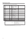
[E]
ENH H. ENHANCE: ∗∗∗ Adjusts H ENHANCE. ‡‡
ENV V. ENHANCE: ∗∗∗ Adjusts V ENHANCE. ‡‡
ESV ENERGY SAVE: ∗∗∗∗∗∗∗∗ Displays the current ENERGY SAVE setting. ¶
ESVS00 ENERGY SAVE: STANDARD Sets the ENERGY SAVE setting to STANDARD. ‡
ESVS01 ENERGY SAVE: MODE1
Sets the ENERGY SAVE setting to MODE 1 (energy saving).
‡
ESVS02 ENERGY SAVE: MODE2
Sets the ENERGY SAVE setting to MODE 2 (energy saving).
‡
ESVS03 ENERGY SAVE: MODE3
Sets the ENERGY SAVE setting to MODE 3 (long life).
‡
ESVS04 ENERGY SAVE: AUTO Sets the ENERGY SAVE setting to AUTO. ‡
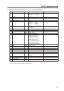
[F]
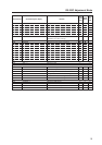
FCA FAN: AUTO Sets the fan rpm control to AUTO. ‡
FCL ######### Displays the current FUNCTIONAL LOCK setting. ¶
FCLS00 LOCK OFF Clears the FUNCTIONAL LOCK. ‡
FCLS01 BUTTONS LOCK Inhibits the main-control panel button control. ‡
FCLS02 IR LOCK Inhibits remote-control button control. ‡
FCLS03 BUTTONS&IR LOCK
Inhibits both main-control panel and remote-control button control.
‡
FCLS04 MEMORY LOCK Sets the MEMORY LOCK. ‡
FCM FAN: MAX Sets the fan rpm control to maximum. ‡
FDT FUNCTION DEFAULT Executes FUCNTION DEFAULT. ¶
FMK SCREEN MASK: ##### Displays the current SCREEN MASK setting. ¶
FMKS00 SCREEN MASK: OFF Sets the SCREEN MASK to OFF. ‡
FMKS02 SCREEN MASK: INVERSE
Sets the SCREEN MASK to INVERSE (negative-positive inversion).
‡
FMKS03 SCREEN MASK: WHITE Turns ON the WHITE mask. ‡
FMKS04 SCREEN MASK: RED Turns ON the RED mask. ‡
FMKS05 SCREEN MASK: GREEN Turns ON the GREEN mask. ‡
FMKS06 SCREEN MASK: BLUE Turns ON the BLUE mask. ‡
FMKS07 SCREEN MASK: YELLOW Turns ON the YELLOW mask. ‡
FRC FRC: ##### Displays the current FRC setting. ¶
FRCS01 FRC: MODE1 Sets FRC to MODE 1. ‡
FRCS02 FRC: MODE2 Sets FRC to MODE 2. ‡
FRCS03 FRC: MODE3 Sets FRC to MODE 3. ‡
FRP FRESH POSITION
Initializes the integrator and SCREEN adjustment values.
‡
FXO AUDIO OUT: FIX Selects fixed audio output. ‡
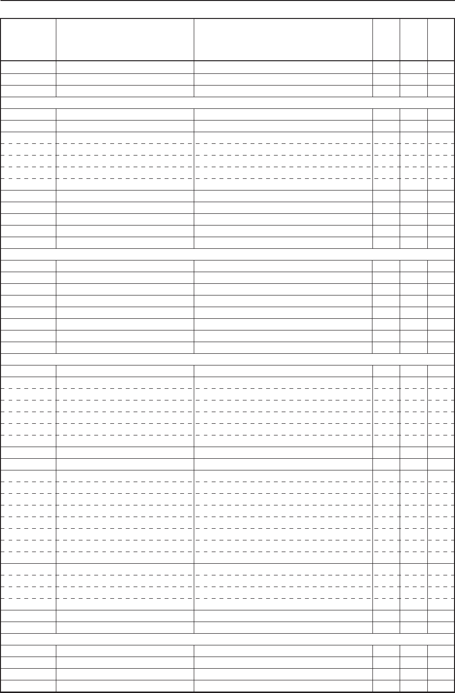
[G] ## GET commands are valid in any state including STB (except for [GPI], [GPS], [GSS], [GWB]).
GHI G HIGH: ∗∗∗ Adjusts G HIGH. ‡‡
GLW G LOW: ∗∗∗ Adjusts G LOW. ‡‡
GPI (GET PICTURE DATA) Gets integrator PICTURE data. ¶¶
GPS (GET POSITION DATA) Gets integrator SCREEN data. ¶¶
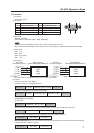
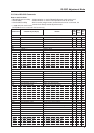
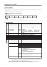
Command name AJY (232C integrator) Display
RS-232C
Adjustment
Validity
Normal
Validity
Numerical
Direct
Validity
Remarks