


10
En
Installation and Connections
English
Installation and Connections
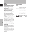
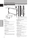
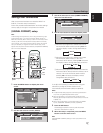
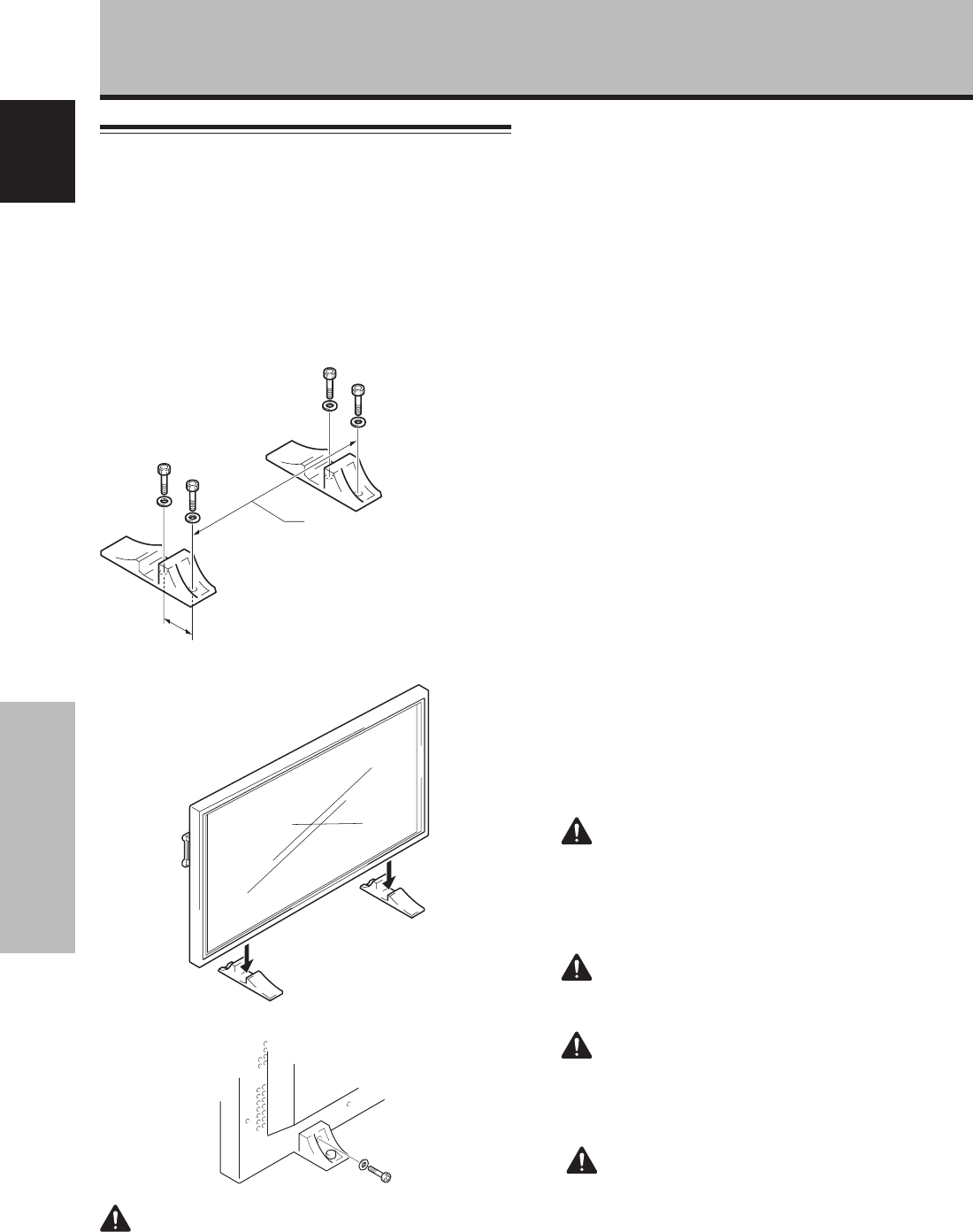
Installation of the unit
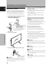
Installation using the supplied display stands
Be sure to fix the supplied stands to the installation surface.
Use commercially available M8 bolts that are 25 mm
(1 in.) longer than the thickness of the installation surface.
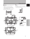
1 Fix the supplied stands to the installation surface
at each of the 4 prepared holes using
commercially available M8 bolts.
2 Set this unit in the stands.
3 Fix this unit using the supplied washer and bolt.
Front
Rear
PDP-504CMX: 798 mm (31-
7
/16 in.)
(Bolt hole thread pitch)
PDP-434CMX: 880 mm (31-
7
/16 in.)
(Bolt hole thread pitch)
110 mm (4-
5
/16 in.)
Use a 6 mm (
1
/4 in.) hex
wrench to bolt them.
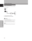
CAUTION
This display unit weighs at least 30 kg (67 lbs) and has little front-
to-back depth, making it very unstable when stood on edge. As a
result, two or more persons should cooperate when unpacking,
moving, or installing the display.
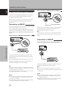
Installation using the optional PIONEER stand or
installation bracket
÷ Please be sure to request installation or mounting of this unit
or the installation bracket by an installation specialist or the
dealer where purchased.
÷ When installing, be sure to use the bolts provided with the
stand or installation bracket.
÷ For details concerning installation, please refer to the
instruction manual provided with the stand or installation
bracket.
Installation using accessories other than the
PIONEER stand or installation bracket (sold
separately)
÷ When possible, please install using parts and accessories
manufactured by PIONEER. PIONEER will not be held
responsible for accident or damage caused by the use of parts
and accessories manufactured by other companies.
÷ For custom installation, please consult the dealer where the
unit was purchased, or a qualified installer.
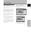
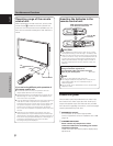
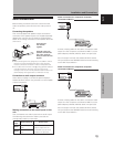
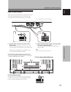
Wall-mount installation of the unit
This unit has been designed with bolt holes for
wall-mount installation, etc. The installation holes
provided are shown in the accompanying illustration.
÷ Be sure to attach in 4 or more locations above and
below, left and right of the center line.
÷ Use bolts that are long enough to be inserted 12 mm
(
1
/2 in.) to 18 mm (
11
/16 in.) into the main unit from the
attaching surface for both a holes and b holes. Refer to
the side view diagram in the accompanying illustration.
÷ As this unit is constructed with glass, be sure to install
it on a flat, unwarped surface.
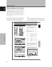
CAUTION
To avoid malfunction, overheating of this unit, and possible fire
hazard, make sure that the vents on the main unit are not
blocked when installing. Also, as hot air is expelled from the air
vents, be careful of deterioration and dirt build up on rear surface
wall, etc..
CAUTION
Please be sure to use an M8 (Pitch = 1.25 mm) bolt. (Only this
size bolt can be used.)
CAUTION
This display unit weighs at least 30 kg (67 lbs) and has little front-
to-back depth, making it very unstable when stood on edge. As a
result, two or more persons should cooperate when unpacking,
moving, or installing the display.
CAUTION
This unit incorporates a thin design. To ensure safety if vibrated
or shaken, please be sure to take measures to prevent the unit
from tipping over.
Always install the supplied display stands
according to the dimensions shown in
the accompanying illustration.