


42
En
Additional Information
English
Additional Information
51
15 11
6
10
Explanation of terms
Aspect ratio
The TV screen’s width to height ratio is referred to as its aspect
ratio. The aspect ratio on standard TVs is 4:3 and on wide TVs or
High Definition TVs it is 16:9.
G ON SYNC
This indicates a video signal in the form of a synchronization
signal added to the G (GREEN) signal of the R.G.B signal.
VGA
General term for “Video Graphics Array”.
Generally this indicates a 640 dot x 480 line resolution.
WVGA
General term for “Wide Video Graphics Array”.
Generally this indicates a 848 dot x 480 line resolution.
XGA
General term for “eXtended Graphics Array”.
Generally this indicates a 1024 dot x 768 line resolution.
WXGA
General term for “Wide eXtended Graphics Array”.
Generally this indicates a 1280 dot x 768 line resolution.
SXGA
General term for “Super eXtended Graphics Array”.
Generally this indicates a 1280 dot x 1024 line resolution.
SXGA+
General term for “Super eXtended Graphics Array plus”.
Generally this indicates a 1400 dot x 1050 line resolution.
DVI
General term for “Digital Visual Interface”. An interface standard
proposed by the Digital Display Working Group (DDWG) for
digital displays.
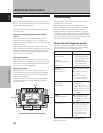
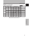
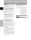
Appendix 2: INPUT1/2 pin assignments
Appendix 2-1/2:
INPUT1 (Mini D-sub 15 pin female connector) pin
allocation.
Input Output
1
2
3
4
5
6
7
8
9
10
11
12
13
14
15
R
G
B
NC (No connection)
GND
GND
GND
GND
DDC + 5V
GND
NC (No connection)
DDC SDA
HD or H/V SYNC
VD
DDC SCL
+
+
+
+
+
+
+
+
NC (No connection)
+
+
NC (No connection)
+
+
NC (No connection)
Pin No.
Apple and Macintosh are registered trademarks of Apple
Computer, Inc.
Microsoft is a registered trademark of Microsoft Corporation.
NEC and PC-9800 are trademarks of NEC Corporation.
VESA and DDC are registered trademarks of Video Electronics
Standards Association.
Power Management and Sun Microsystems are registered
trademarks of Sun Microsystems, Inc.
VGA and XGA are registered trademarks of International
Business Machines Co., Inc.
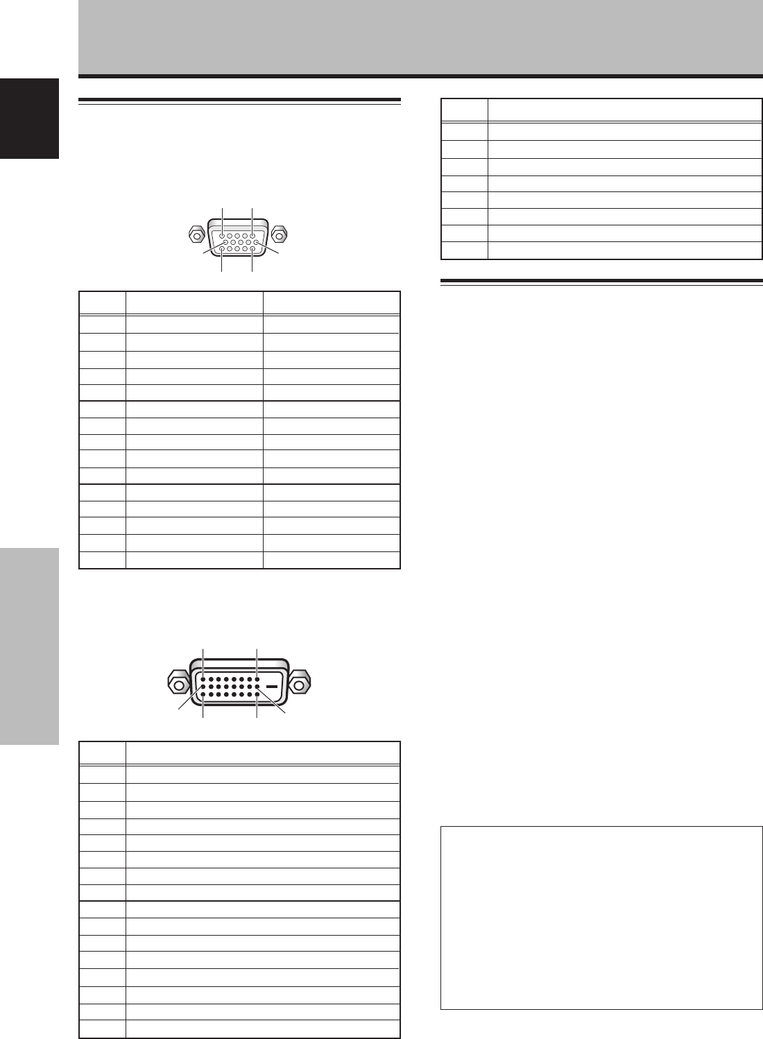
Appendix 2-2/2:
INPUT2 (DVI female connector) pin allocation.
18
2417
9
16
Signal Assignment
1
2
3
4
5
6
7
8
9
10
11
12
13
14
15
16
T.M.D.S. Data2–
T.M.D.S. Data2+
T.M.D.S. Data2/4 Shield
NC (No connection)
NC (No connection)
DDC Clock
DDC Data
NC (No connection)
T.M.D.S. Data1–
T.M.D.S. Data1+
T.M.D.S. Data1/3 Shield
NC (No connection)
NC (No connection)
+5V Power
GND
Hot Plug Detect
Pin No.
Signal Assignment
17
18
19
20
21
22
23
24
T.M.D.S. Data0–
T.M.D.S. Data0+
T.M.D.S. Data0/5 Shield
NC (No connection)
NC (No connection)
T.M.D.S. Clock Shield
T.M.D.S. Clock+
T.M.D.S. Clock–
Pin No.
Published by Pioneer Corporation.
Copyright © 2004 Pioneer Corporation.
All rights reserved.