


13
1
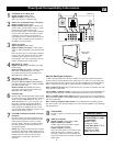
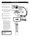
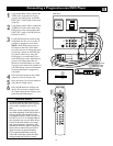
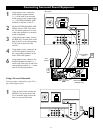
Using Audio/Video cables, connect the
YPbPr jacks on the back of the pro-
gressive-scan DVD player to the HD
INPUT-AV 3 Y Pb Pr jacks on the back
of the TV.
2
Using Stereo Audio cables, connect the
AUDIO OUT jacks on the back of the
DVD player to the corresponding HD
INPUT-AV 3 audio (L and R) jacks on
the back of the TV.
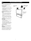
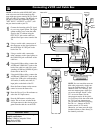
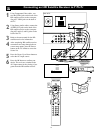
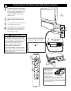
3
If your DVD player has an I/P switch
on the back, be sure it is set to the “P”
position for progressive-scan mode.
NOTE: Some DVD players have an
I/P switch on the back, while others
may allow the user to change the mode
by pressing a button on the DVD play-
er’s remote control or by using the
DVD player’s on-screen menu. Also,
some DVD players have dedicated pro-
gressive-scan output jacks that are
labeled as such and require no switch-
ing by the user. See the user manual for
your DVD player for more information
on placing the player in progressive-
scan mode.
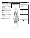
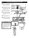
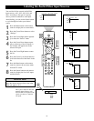
4
Press the Source button on the remote
control to access the Source list.
5
Press the Cursor Up or Down button to
select the AV3 input source.
6
Press the OK button to confirm your
choice. The set is now switched to the
AV3 input source for the viewing of pro-
grams from the DVD player.
Connecting a Progressive-scan DVD Player
VIDEO
S-VIDEO
L
Pb
Pr
VIDEO
S-VIDEO
L
AUDIO
L
R
AUDIO
L
R
G/Y
R/Pr
B/Pb
V
H
SYNC
L
R
AUDIO
L
R
AUDIO
HD INPUT-AV 3
HD INPUT-AV 4
INPUT-AV 2 SUBWOOFEROUTPUTINPUT-AV 1
Y
AMP SWITCH
CENTER CHANNEL AMP INPUT
ANTENNA IN 75Ω
EXT INT
+
_
DVI
OPTICAL
COAXIAL
DIGITAL
BITSTREAM
/PCM
AUDIO OUT
2CH
L
R
AC IN ~
VIDEO OUT
SELECT
I
P
Y
P
B
PR
VIDEO
S
OPEN/CLOSE
STANDBY-ON
STOP
PREV NEXT
PLAY PAUSE
DVD619 DVD/CD PLAYER
Source
OK
2
1
5
4
5
6
3
TV
AV1:None
CVI: None
AV2:None
AV3:None
AV4:None
SIDE:None
• To simplify making connections, the con-
nectors on audio and video cables are often
color coded to match the colors on TV
jacks.
• The names for the component video jacks
may differ depending on the DVD player or
accessory digital source equipment used.
For example, besides Y Pb Pr, you may see
R-Y/B-Y/Y; or Cr Cb Y. Although abbrevia-
tions and terms may vary, the letters B and
R stand for the blue and red color compo-
nent signal connectors, respectively, and Y
indicates the luminance signal. If necessary,
refer to the user manual for your DVD or
digital accessory for more information.
• If you experience difficulties receiving
sound with a DVD disc, check the sound
settings through the DVD disc’s menu.
HELPFUL HINTS
Back of TV
Back of Progressive-
scan DVD Player
(example only)