


Making Connections
13
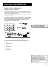
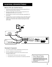
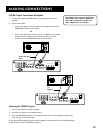
ANTENNA/
CABLE INPUT
POWER
VIDEO
AUDIO
L
R
INPUT1
INPUT2
INPUT3
S-VIDEO
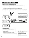
(S)VGA 1
STEREO INPUT
(S)VGA 2
AUDIO INPUTS
L
R
AUDIO OUTPUTS
FIXED
VARIABLE
LR L
R
EXT SPEAKERS
EXT
INT
L
R
++
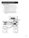
USB
PC/
HUB
DIGITAL TV
INPUT
DEVICE/
HUB
VIDEO
AUDIO
R
SELECTED OUTPUTS
L
AUDIO
R
L
YP
B PR
COMPONENT VIDEO INPUT
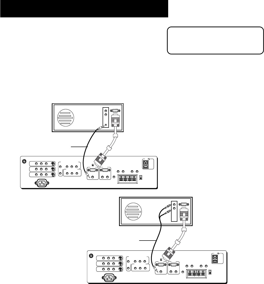
BACK OF COMPUTER
G-LINK
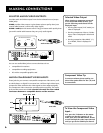
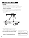
ANTENNA/
CABLE INPUT
POWER
VIDEO
AUDIO
L
R
INPUT1
INPUT2
INPUT3
S-VIDEO
(S)VGA 1
STEREO INPUT
(S)VGA 2
AUDIO INPUTS
L
R
AUDIO OUTPUTS
FIXED
VARIABLE
LR L
R
EXT SPEAKERS
EXT
INT
L
R
++
USB
PC/
HUB
DIGITAL TV
INPUT
DEVICE/
HUB
VIDEO
AUDIO
R
SELECTED OUTPUTS
L
AUDIO
R
L
YP
B
P
R
COMPONENT VIDEO INPUT
BACK OF COMPUTER
G-LINK
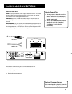
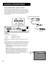
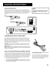
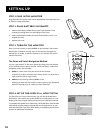
(S)VGA1 Input Connection Examples
1. Connect the supplied (S)VGA cable to your computer and to the
monitor.
2. Connect the audio:
• Connect the stereo mini-jack cable to the computer and to the
STEREO INPUT jack on the monitor.
OR
• Connect the RCA-type connectors of a “Y” adapter to the audio
outputs on the computer, and connect the stereo mini-jack
connector to the STEREO INPUT jack on the monitor.
“Y”
Adapter
Stereo mini-jack
cable
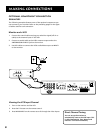
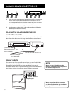
Viewing the (S)VGA1 Input
1. Turn on the monitor and the computer.
2. Press the TV button on the remote control.
3. Press the WHO•INPUT button on the remote control to scroll through the video inputs
until you get to the VGA1 input.
(If you have difficulty getting your screen to appear on the monitor, see the Troubleshooting
section of this manual for possible solutions.)
The (S)VGA1 input supports DDC2B and
VESA DPMS when using an appropriate
cable. We recommend using the VGA
cable supplied with this monitor.