


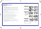
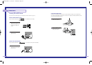
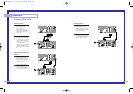

Connecting a DTV Set Top Box
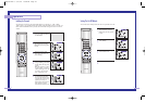
Connecting to Y,Pb,Pr
1
Connect a set of audio
cables between the
Component2 or
Component3 AUDIO IN
jacks on the TV and the
AUDIO OUT jacks on the
Set Top Box.
2
Connect video cables
between the Component2
or Component3 Y, P
b
and P
r
inputs on the TV and Y, P
b
and P
r
(or Y, C
b
, C
r
) outputs
on the Set Top Box.
Note: For an explanation of
Component video, see your
Set Top Box owner's manu-
al.
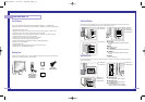
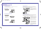
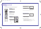
Connecting to DVI (Digital Visual
Interface)
1
Connect a set of audio
cables between the PC
AUDIO IN jacks on the TV
and the AUDIO OUT jacks
on the Set Top Box.
2
Connect video cables
between the DVI IN jack on
the TV and the DVI OUT
jack on the Set Top Box.
27
Connections
26
Component1
(480i/480p)
Component1/2
(480p/720p/10801i)
Y
P
b
P
r
L
R
L
R
PC AUDIO
DTV Set Top Box
ANT-A
ANT A-OUT
ANT-B
S-VIDEO 1 S-VIDEO 2
VLR
MONITOR
OUT
VIDEO
2
VIDEO
1
DVI
PC
RS-232C
TV Rear Panel
Component1
(480i/480p)
Component1/2
(480p/720p/10801i)
Y
P
b
P
r
L
R
L
R
PC AUDIO
DTV Set Top Box
ANT-A
ANT A-OUT
ANT-B
S-VIDEO 1 S-VIDEO 2
VLR
MONITOR
OUT
VIDEO
2
VIDEO
1
DVI
PC
RS-232C
TV Rear Panel
DVI
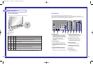
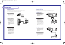
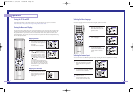
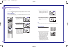
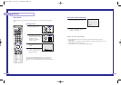
Connecting to R,G,B
1
Connect a set of audio
cables between the PC
AUDIO IN jacks on the TV
and the AUDIO OUT jacks
on the Set Top Box.
2
Connect video cables
between the PC IN jack on
the TV and the R.G.B OUT
jack on the Set Top Box.
Component1
(480i/480p)
Component1/2
(480p/720p/10801i)
Y
P
b
P
r
L
R
L
R
PC AUDIO
DTV Set Top Box
ANT-A
ANT A-OUT
ANT-B
S-VIDEO 1 S-VIDEO 2
VLR
MONITOR
OUT
VIDEO
2
VIDEO
1
DVI
PC
RS-232C
TV Rear Panel
DVI
BP68-00142A-2 5/27/03 10:09 AM Page 26